
HHR L4-2.2L (2007)
Brake Rotor/Disc: Testing and Inspection
Brake Rotor Assembled Lateral Runout Correction - Correction Plates
Brake Rotor Assembled Lateral Runout Correction - Correction Plates
Tools Required
*
J 39544-KIT Complete Torque Socket Set-10 Pieces, or equivalent
*
J 45101-100 Conical Brake Rotor Washers
Caution: Refer to Brake Dust Caution.
Important:
*
Brake rotor thickness variation MUST be checked BEFORE checking for assembled lateral runout (LRO). Thickness variation exceeding
the maximum acceptable level can cause brake pulsation.
*
Brake rotor assembled LRO exceeding the maximum allowable specification can cause thickness variation to develop in the brake rotor
over time, usually between 4 800-11 300 km (3,000-7,000 mi).
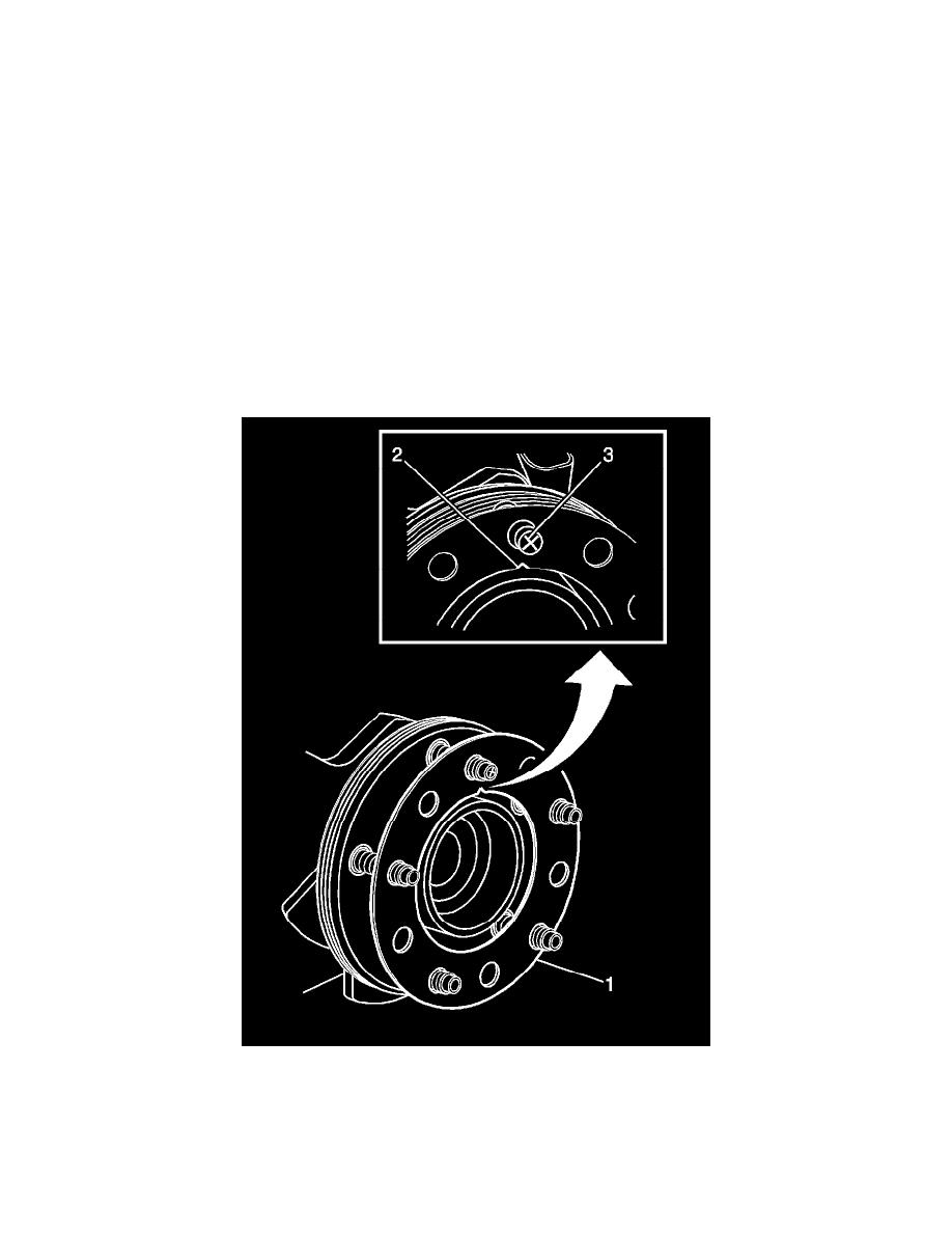
1. Rotate the brake rotor to position the high spot, identified and marked during the brake rotor assembled LRO measurement procedure, to face
upward.
2. Remove the J 45101-100 and the lug nuts that were installed during the assembled LRO measurement procedure and/or the indexing correction
procedure.
3. Inspect the mounting surface of the hub/axle flange and the brake rotor to ensure that there are no foreign particles or debris remaining.
4. Select the correction plate, following the manufacturer's instructions, which has a specification closest to the assembled LRO measurement.
For example: If the assembled LRO measurement was 0.076 mm (0.003 in), the 0.076 mm (0.003 in) correction plate would be used. If the