
HHR L4-2.2L (2007)
Circuit/System Description
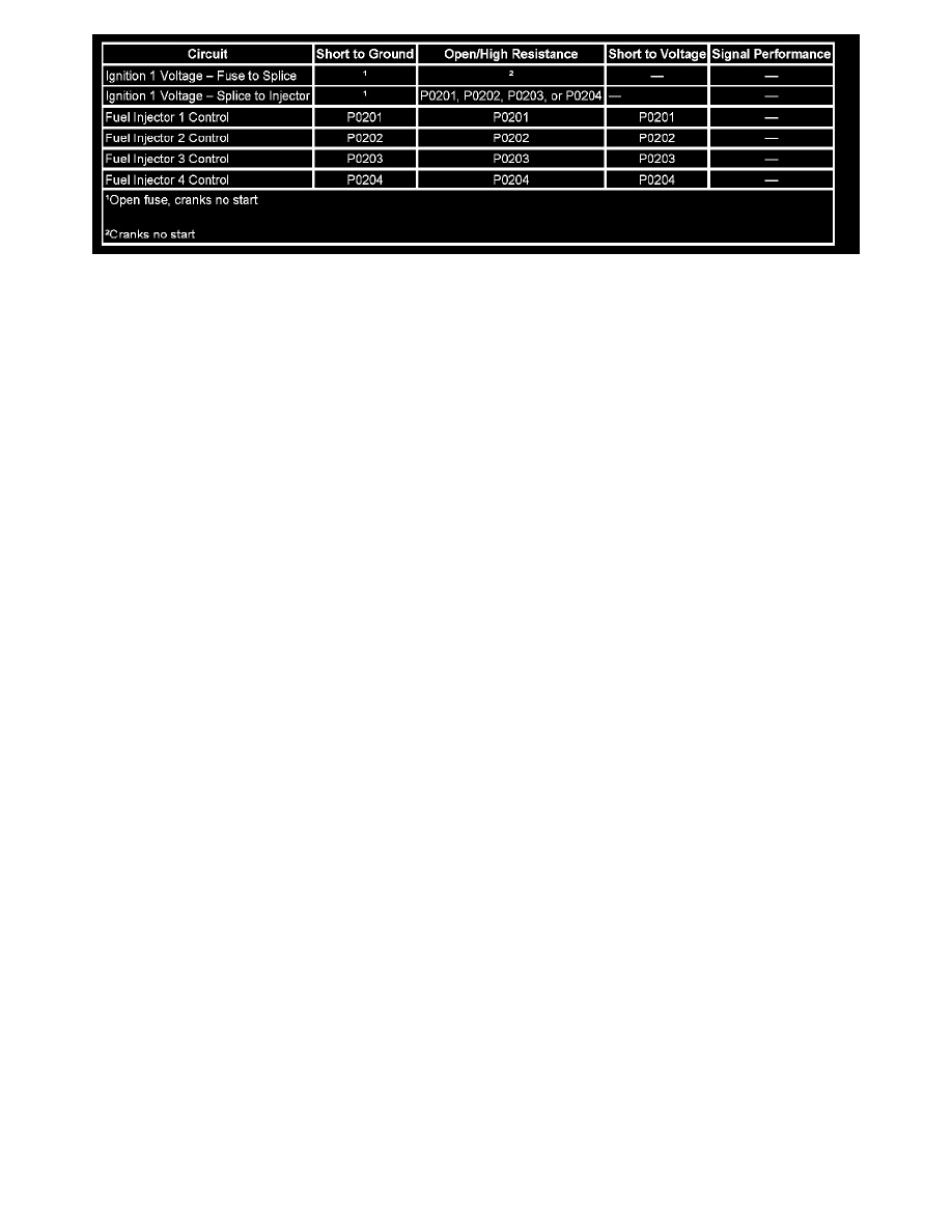
The control module enables the appropriate fuel injector pulse for each cylinder. Ignition voltage is supplied to the fuel injectors. The control module
controls each fuel injector by grounding the control circuit via a solid state device called a driver.
Circuit/System Testing
1. Ignition OFF, disconnect the harness connector at a fuel injector.
2. Ignition ON, verify that a test lamp illuminates between the ignition circuit terminal 1 or A and ground.
‹› If the test lamp does not illuminate, test the ignition circuit for a short to ground or an open/high resistance. If the circuit tests normal and the
ignition circuit fuse is open, test or replace the fuel injector.
3. Ignition OFF, connect a J 44603 between the control circuit terminal 2 or B and the ignition circuit terminal 1 or A of each fuel injector, one at a
time.
4. Engine cranking, the test lamp should flash for each injector.
‹› If the test lamp is always ON, test the appropriate control circuit for a short to ground. If the circuit tests normal, replace the ECM.
‹› If the test lamp is always OFF, test the appropriate control circuit for a short to voltage or an open/high resistance. If the circuit tests normal,
replace the ECM.
5. If all circuits test normal, test or replace the fuel injector. Refer to Fuel Injector Diagnosis (w/J39021 or w/Tech 2) Fuel Injector Diagnosis
(w/CH47976). See: Computers and Control Systems/Testing and Inspection/Component Tests and General Diagnostics/Fuel Injector Diagnosis
(w/J39021 or w/Tech 2) See: Computers and Control Systems/Testing and Inspection/Component Tests and General Diagnostics/Fuel Injector
Diagnosis (With CH 47976)
Repair Instructions
Perform the Diagnostic Repair Verification after completing the diagnostic procedure. See: Computers and Control Systems/Testing and
Inspection/Diagnostic Trouble Code Tests and Associated Procedures/Verification Tests and Procedures
* Control Module References for ECM replacement, setup, and programming See: Testing and Inspection/Programming and Relearning
* Fuel Injector Replacement
Fuel Injector Coil Test (w/CH47976)
Fuel Injector Coil Test
Verify the resistance of each fuel injector with one of the following methods:
* If the engine coolant temperature (ECT) sensor is between 10-32°C (50-90°F), the resistance of each fuel injector should be 11-14 ohms.
‹› If the injectors measure OK, perform the AFIT Test Procedure.
‹› If not within the specified range, replace the fuel injector.
* If the ECT sensor is not between 10-32°C (50-90°F), measure and record the resistance of each fuel injector with a DMM. Subtract the lowest
resistance value from the highest resistance value. The difference between the lowest value and the highest value should be equal to or less than 3
ohms.
‹› If the difference is equal to or less than 3 ohms, refer to the AFIT Test Procedure.
‹› If the difference is more than 3 ohms, add all of the fuel injector resistance values to obtain a total resistance value. Divide the total resistance