
Impala V6-3.4L VIN E (2000)
9. Stake the front head at 3 places 120 degrees apart in order to ensure that the clutch coil remains in position.
10. Ensure that the stake size is only one half of the area of the punch tip and only 0.28-0.35 mm (0.010-0.015 in) in depth.
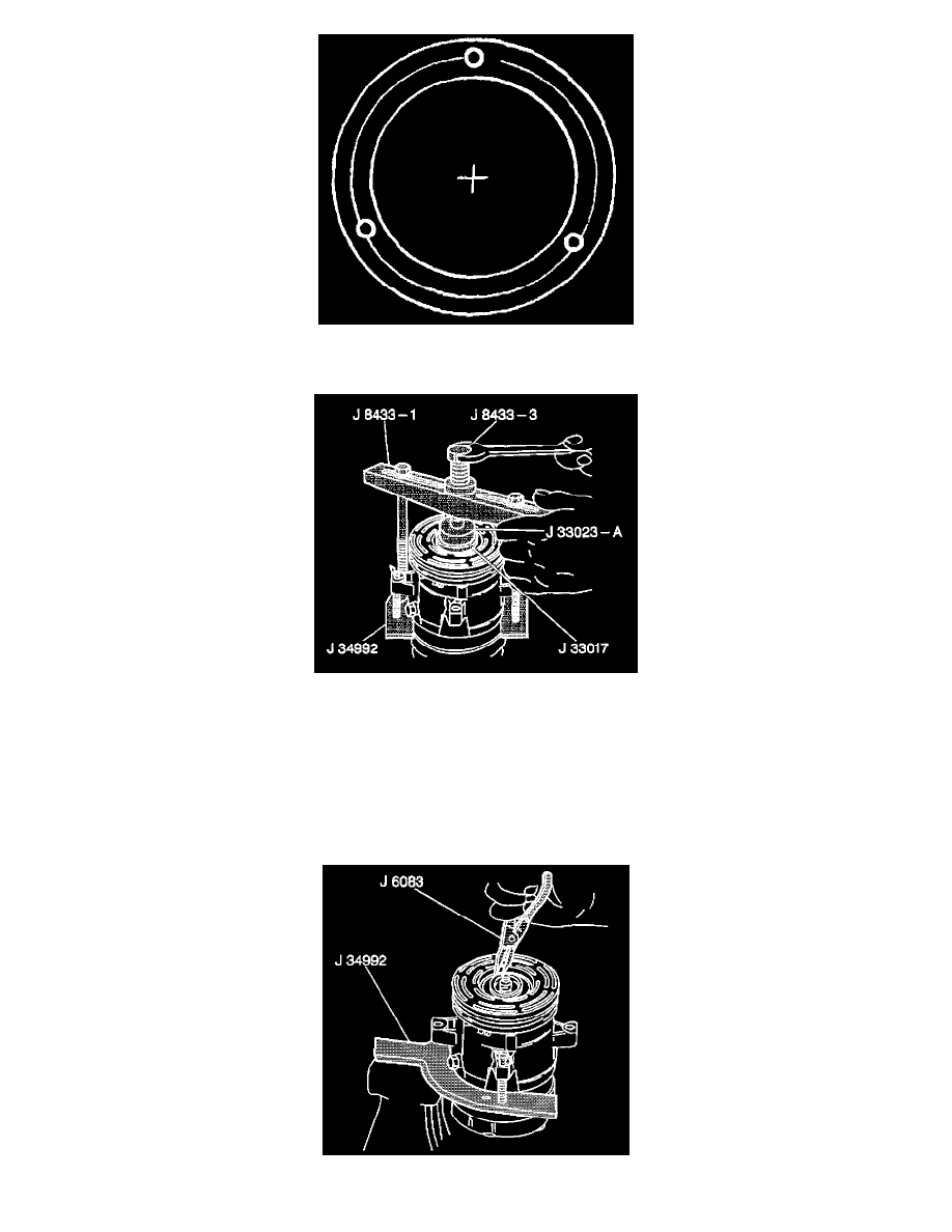
11. With the compressor mounted to the J 34992, position the rotor and bearing assembly on the front head.
12. Position the J 33017 and the J 33023-A directly over the inner race of the bearing.
13. Position the J 8433-1 on the J 33023-A.
14. Assemble the two through bolts and the washers of the J 34992 through the slots of the J 8433-1.
15. Thread the two through bolts into the J 34992. Ensure that the thread of the through bolts engages the full thickness of the J 34992.
16. Tighten the J 8433-3 in the J 8433-1 in order to force the pulley rotor and bearing assembly onto the front head of the compressor.
17. If the J 33017 slips off direct, in-line contact with inner face of the bearing, use the following steps:
17.1. Loosen the J 8433-3.
17.2. Realign the J 33017 and the J 33023-A in order to ensure that the installer clears the front head.
18. Install the rotor and bearing assembly retainer ring using the J6083.