
Impala V6-3.8L SC VIN 1 (2005)
8. Measure the assembled LRO of the brake rotor. Refer to Brake Rotor Assembled Lateral Runout (LRO) Measurement.
See: Testing and Inspection/Component Tests and General Diagnostics/Brake Rotor Assembled Lateral Runout (LRO) Measurement
9. Compare the amount of change between this measurement and the original measurement.
10. If this measurement is within specifications, proceed to step 14.
11. If this measurement still exceeds specifications, repeat steps 1-9 until the best assembled LRO measurement is obtained.
12. Matchmark the final location of the rotor to the wheel studs if the orientation is different than it was originally.
13. If the brake rotor assembled LRO measurement still exceeds the maximum allowable specification, refer to Brake Rotor Assembled Lateral
Runout (LRO) Correction.
See: Brake Rotor Assembled Lateral Runout (LRO) Correction
14. If the brake rotor assembled LRO is within specification, install the brake caliper and depress the brake pedal several times to secure the rotor in
place before removing the J45101-100 and the lug nuts.
Correction Plates
BRAKE ROTOR ASSEMBLED LATERAL RUNOUT (LRO) CORRECTION - CORRECTION PLATES
Tools Required
^
J 39544-KJT Torque-Limiting Socket Set, or equivalent
^
J 45101-100 Conical Brake Rotor Washers
Important:
^
Brake rotor thickness variation MUST be checked BEFORE checking for assembled lateral runout (LRO). Thickness variation exceeding the
maximum acceptable level can cause brake pulsation. Refer to Brake Rotor Thickness Variation Measurement on page 5-5&
^
Brake rotor assembled lateral runout (LRO) exceeding the maximum allowable specification can cause thickness variation to develop in the brake
rotor over time, usually between 4 800-11 300 km (3,000-7,000 mi). Refer to Brake Rotor Assembled Lateral Runout (LRO) Measurement.
See: Testing and Inspection/Component Tests and General Diagnostics/Brake Rotor Assembled Lateral Runout (LRO) Measurement
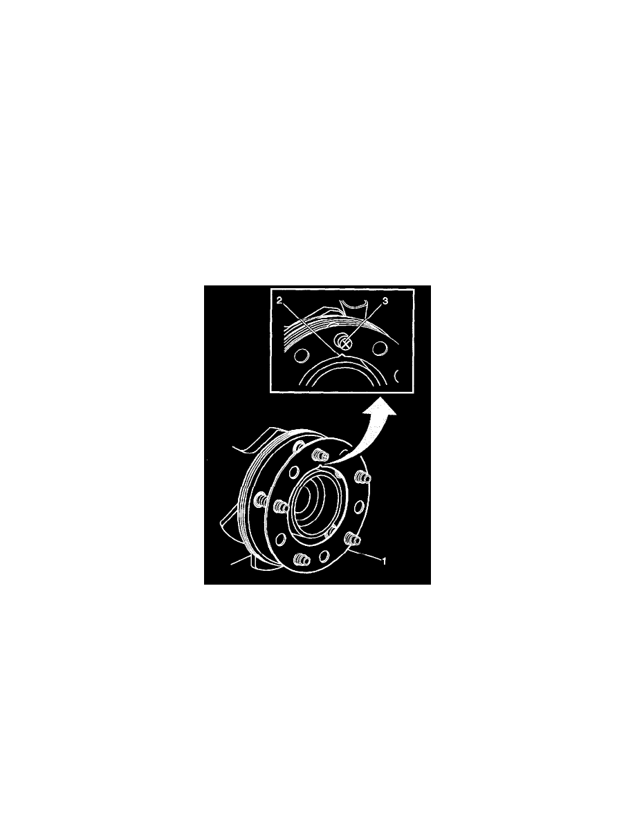
1. Rotate the brake rotor to position the high spot, identified and marked during the brake rotor assembled LRO measurement procedure, to face
upward.
2. Remove the J 45101-100 and the lug nuts that were installed during the assembled LRO measurement procedure and/or the indexing correction
procedure.