
Impala V6-3.8L SC VIN 1 (2005)
Oxygen Sensor: Service and Repair
Heated Oxygen Sensor (HO2S) 1 Replacement
HEATED OXYGEN SENSOR (HO2S) 1 REPLACEMENT
TOOLS REQUIRED
J 39194 Oxygen Sensor Wrench
NOTE: The Heated Oxygen Sensor (HO2S) and the Oxygen Sensor use a permanently attached pigtail and connector. Do not remove this pigtail
from the Heated Oxygen Sensor. Damage or the removal of the pigtail or the connector could affect the proper operation of the sensor.
Take care when handling the HO2S and the O2S. Keep the in-line electrical connector and the louvered end free of grease, dirt, or other contaminants.
Also avoid using cleaning solvents of any type. Do not drop the HO2S or the O2S. Do not roughly handle the HO2S or the O2S.
REMOVAL PROCEDURE
1. Remove the fuel injector sight shield.
NOTE: The oxygen sensor may be difficult to remove when the engine temperature is below 48°C (120°F). Excessive force may damage threads in
the exhaust manifold or the exhaust pipe.
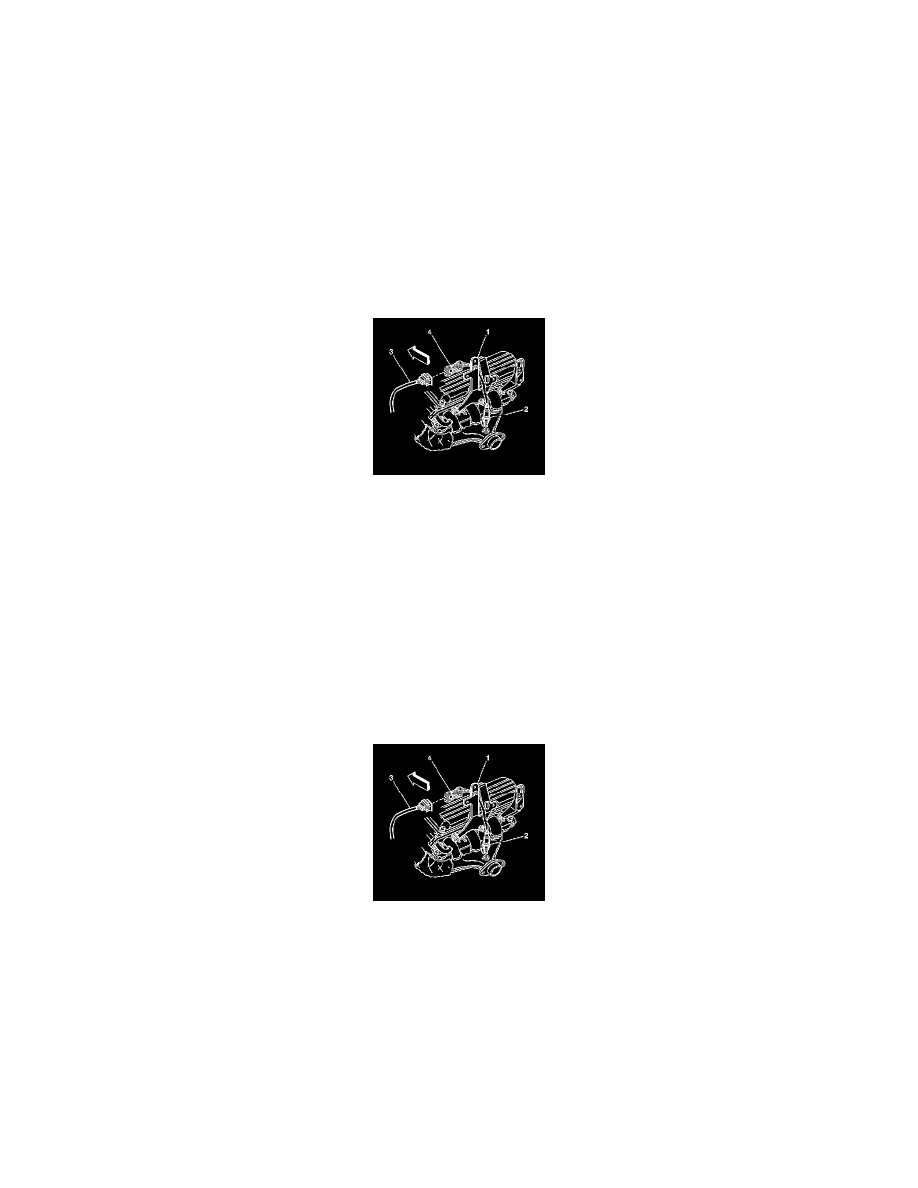
2. Remove the heated oxygen sensor (HO2S) electrical CPA retainer.
3. Disconnect the HO2S wiring harness connector (3) from the HO2S electrical connector (4).
4. Remove the HO2S electrical connector (4) from the fuel injector sight shield bracket (1).
5. Use the J 39194 to remove the HO2S (2).
IMPORTANT: Remove the oxygen sensor with the engine temperature above 48°C (120°F). Otherwise the oxygen sensors may be difficult to
remove.
INSTALLATION PROCEDURE
1. Install the rear oxygen sensor in the right exhaust manifold.
NOTE: Refer to Fastener Notice in Service Precautions.
IMPORTANT: A special anti-seize compound is used on the oxygen sensor (1) threads. New service sensors should already have the compound
applied to the threads. Coat the threads of a reused sensor with anti-seize compound P/N 12377953 or equivalent.
Use the J 39194 to tighten the HO2S to 41 N.m (30 lb ft).
2. Connect the HO2S electrical connector (4) to the wiring harness connector (3).
3. Install the HO2S electrical connector (4) to the fuel injector sight shield bracket (1).
4. Install the HO2S electrical CPA retainer.
5. Install the fuel injector sight shield.