
Impala V6-3.8L SC VIN 1 (2005)
-
Perform one of the following items in order to find the correct wire size:
-
Find the wire on the schematic and convert the metric size to the equivalent american wire gage (AWG) size.
-
Use an AWG wire gage.
-
If you are unsure of the wire size, begin with the largest opening in the wire stripper and work down until achieving a clean strip of the
insulation.
-
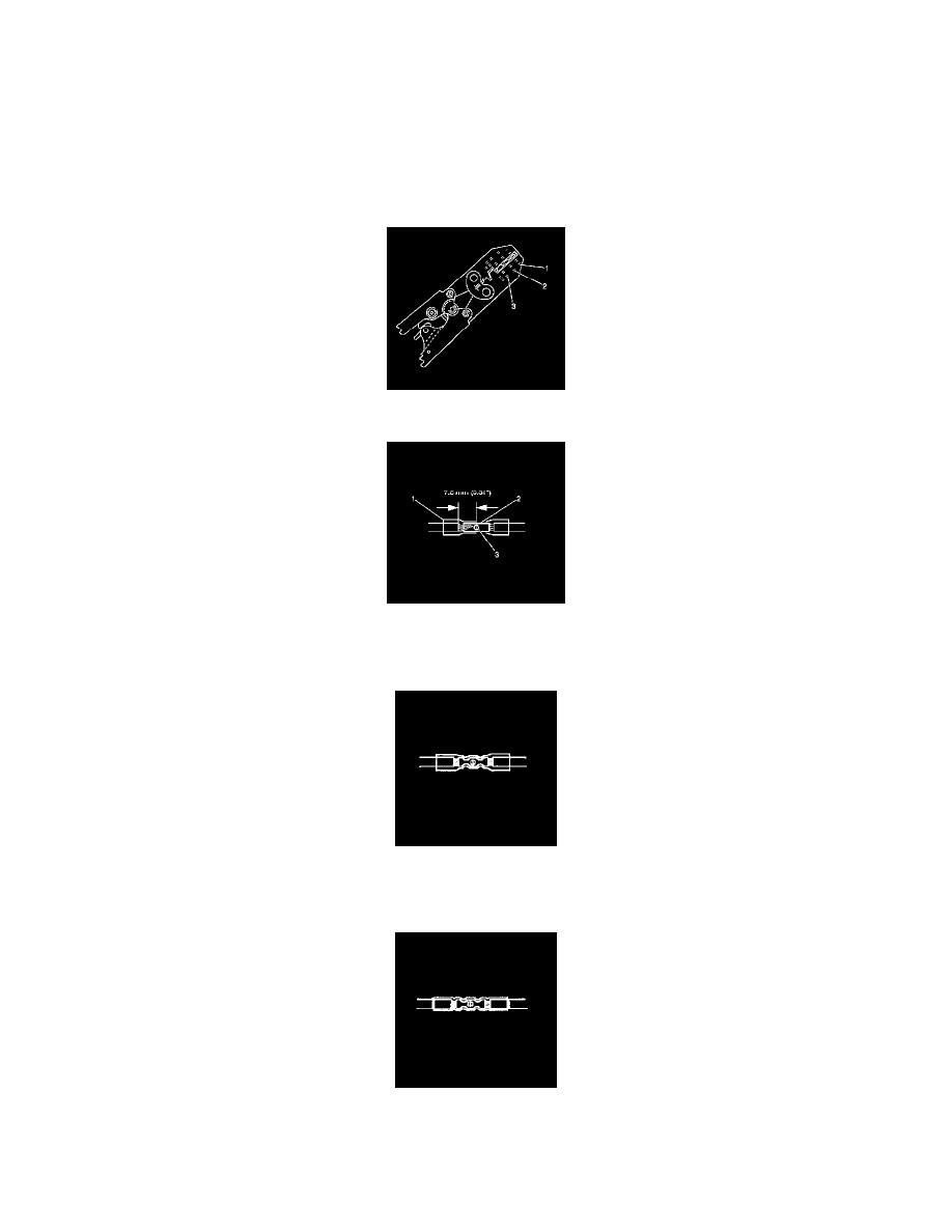
Strip approximately 7.5 mm (0.313 in) of insulation from each wire to be spliced.
-
Do not nick or cut any of the strands. Inspect the stripped wire for nicks or cut strands.
-
If the wire is damaged, repeat this procedure after removing the damaged section.
4. Select the proper duraseal splice sleeve according to the wire size. Refer to the above table at the beginning of the repair procedure for the color
coding of the duraseal splice sleeves and the crimp tool nests.
5. Use the Splice Crimp Tool from the J-38125 in order to position the duraseal splice sleeve in the proper color nest of the Splice Crimp Tool.
6. Place the duraseal splice sleeve in the nest. Ensure that the crimp falls midway between the end of the barrel and the stop. The sleeve has a stop (3)
in the middle of the barrel (2) in order to prevent the wire (1) from going further. Close the hand crimper handles slightly in order to firmly hold
the duraseal splice sleeve in the proper nest.
7. Insert the wire into the splice sleeve barrel until the wire hits the barrel stop.
8. Tightly close the handles of the crimp tool until the crimper handles open when released.The crimper handles will not open until you apply the
proper amount of pressure to the splice sleeve. Repeat steps 4 and 5 for the opposite end of the splice.
9. Using the heat torch, apply heat to the crimped area of the barrel.
10. Start in the middle and gradually move the heat barrel to the open ends of the tubing:
-
The tubing will shrink completely as the heat is moved along the insulation.
-
A small amount of sealant will come out of the end of the tubing when sufficient shrinkage is achieved.
Heated Oxygen Sensor (HO2S) Wiring Repairs