
Impala V8-5.3L (2008)
Caution: Refer to Restraint System Service Precautions.
Disable the inflatable restraint steering wheel module when performing this diagnostic. Refer to SIR Disabling and Enabling.
1. Ignition OFF, remove the inflatable restraint steering wheel module.
2. Disconnect the harness connector of the cruise control switch.
3. Ignition ON, measure for 10 volts or greater between the steering wheel switch harness terminal 1 and ground.
‹› If less than 10 volts, test for an open/high resistance or a short to ground on the cruise control supply voltage circuit.
4. Ignition OFF, disconnect the harness connector X1 at the BCM.
5. Test for 1.0 ohm or less resistance between the cruise control switch harness terminal 3 and the BCM X1 connector terminal 3.
‹› If greater than the specified range, test the cruise control switch signal circuit for an open/high resistance.
6. Test for infinite resistance between the cruise control switch harness terminal 3 and ground.
‹› If less than the specified range, test the cruise control switch signal circuit for a short to ground.
7. Ignition ON, test for 0 volts between the cruise control switch harness terminal 3 and ground.
‹› If greater than the specified value, test the cruise control switch signal circuit for a short to voltage.
8. If all circuits test normal, test the component. If the component tests normal, replace the BCM.
Component Testing
Caution: Refer to Restraint System Service Precautions.
Disable the inflatable restraint steering wheel module when performing this diagnostic. Refer to SIR Disabling and Enabling.
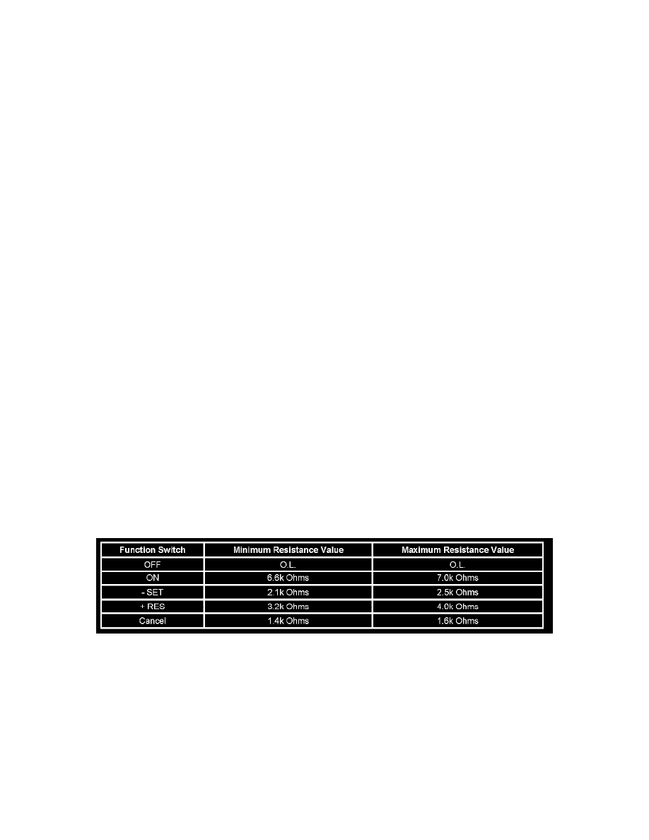
Important: The cruise control switch must be ON in order to properly measure the resistance of the - SET, the + RES, and the Cancel switches.
1. With the ignition OFF, remove the inflatable restraint steering wheel module.
2. With the ignition OFF, disconnect X277 at the inflatable restraint steering wheel module coil.
3. Measure the resistance between terminals E and C at the cruise control switch side of the connector. Individually activate and hold each cruise
control function switch and compare the resistance reading to the values on the schematic for each of the cruise control switches.
‹› If any of the resistance measurements for any of the switches are not within the listed resistance values, replace the cruise control switch
assembly.
Repair Instructions
Perform the Diagnostic Repair Verification after completing the diagnostic procedure. See: Powertrain Management/Computers and Control
Systems/Testing and Inspection/Diagnostic Trouble Code Tests and Associated Procedures/Verification Tests and Procedures
*
Steering Wheel Control Switch Assembly Replacement