
Impala V8-5.3L VIN C (2006)
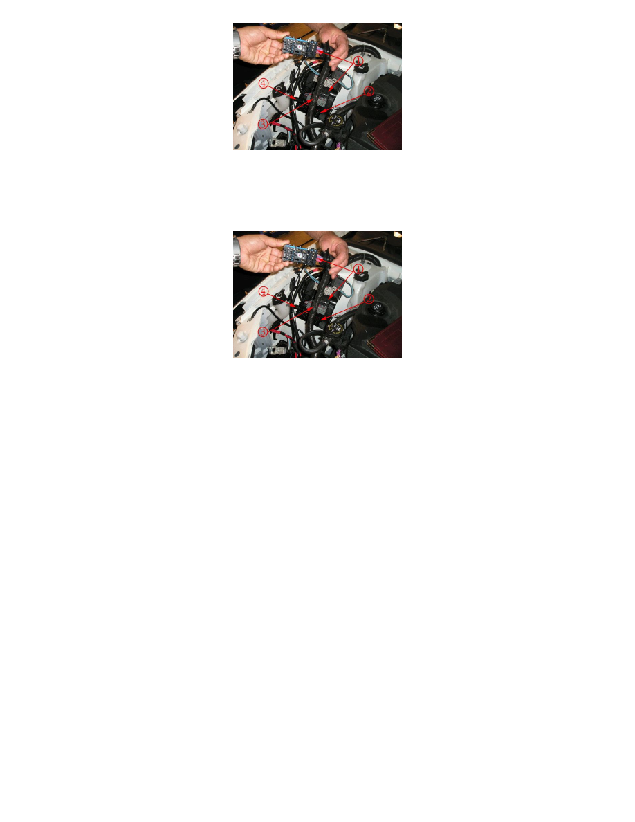
24. Using a suitable tool, open the engine harness conduit (3) for the X1 connector approximately 100 mm (4 in) from the entry point at the fuse block
and extract the:
-
High Speed Cooling Fan Relay Control Circuit
-
Low Speed Cooling Fan Relay Control Circuit
25. Using a suitable tool, open the engine harness conduit (4) for the X3 connector approximately 100 mm (4 in) from the entry point at the fuse block
and extract the:
-
Cooling Fan - Right Supply Voltage Circuit
-
Cooling Fan - Left Low Reference Circuit
-
Cooling Fan - Left Supply Voltage Circuit
Important
Examine the cooling fan supply voltage and low reference circuit wires for discoloration, loss of insulation and brittleness in order to
determine a good point to cut and splice.
26. When performing the following steps, adjust the location of the cuts at least 40 mm (1.5 in) apart in order to allow the splices to lay end to end.
1. Cut both of the fan supply voltage circuits approximately 100 mm (4 in) from the entry point at the fuse block or at a point where the
insulation and flexibility of the wire appear normal.
2. Cut the fan low reference circuit approximately 100 mm (4 in) from the entry point at the fuse block or at a point where the insulation and
flexibility of the wire appear normal.
3. Cut both of the fan relay control circuits approximately 100 mm (4 in) from the entry point at the fuse block.
27. Strip approximately 7.5 mm (0.313 in) of insulation from each of the five wires to be spliced.
1. Do not nick or cut any of the strands. Inspect the stripped wire for nicks or cut strands.
2. If the wire is damaged, repeat this procedure after removing the damaged section.
Note
Adding heat shrink tubing to the wire before splicing is advised in order to protect the integrity of the DuraSeal splices.
28. Compress handles until the ratchet mechanism automatically opens the J-38125-8 Splice Crimp Tool. Place a green DuraSeal splice sleeve in nest
(1) as indicated above. Position the sleeve so that the crimp falls midway between the end of the barrel and the stop. Close the tool handles
slightly in order to firmly hold the splice sleeve in the proper nest (1).