
K 1500 Suburban 4WD V8-4.8L VIN V (2003)
1. If replacing the VCIM, record the 10-digit STID number, and the 11-digit ESN number from the labels on the new module.
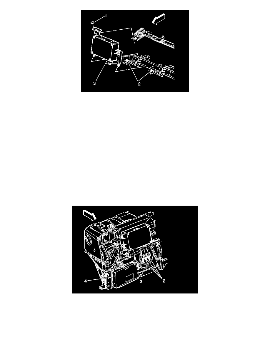
2. Install the VCIM to the mounting brackets.
3. Install the nuts (2).
NOTE: Refer to Fastener Notice in Service Precautions.
Tighten
Tighten the nuts to 2 N.m (18 lb in).
4. Install the VCIM and bracket (3) assembly to the IP.
5. Install the push in retainer (1).
6. Install the VCIM bracket screws (2) to the I/P.
Tighten
Tighten the nuts to 2 N.m (18 lb in).
7. Install the passenger side upper I/P support.
8. Install the I/P upper support screws.
Tighten
Tighten the nuts to 2 N.m (18 lb in).
9. Connect the coaxial cable (3) to the module.
10. Connect the wire connectors (2) to the module.
11. Install the I/P trim panel.
12. Install the scan tool. Use the special functions menu in order to perform the OnStar(r) setup procedure for this vehicle.
IMPORTANT: After replacing the vehicle communication interface module, you must reconfigure the OnStar(r) system. Failure to reconfigure the
system will result in an additional customer visit for repair. In addition, pressing and holding the white dot button on the keypad will NOT reset this
version of the OnStar(r) system. This action will cause a DTC to set.