
K 1500 Suburban 4WD V8-5.3L VIN Z Flex Fuel (2003)
Global Positioning System Module: Service and Repair
COMMUNICATION INTERFACE MODULE REPLACEMENT
REMOVAL PROCEDURE
1. Remove the Instrument Panel (I/P) upper trim panel.
IMPORTANT: The vehicle communication interface module (VCIM) has a specific set of unique numbers that tie the module to each vehicle. These
numbers, the 10-digit station identification and the 11-digit electronic serial number, are used by the National Cellular Network and OnStar(r) to
identify the specific vehicle. Because these numbers are tied to the vehicle identification number of the vehicle, you must never exchange these parts
with those of another vehicle.
2. Open the Instrument panel storage compartment.
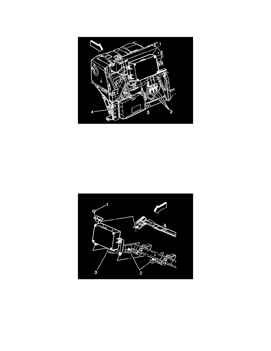
3. Disconnect the wire connectors (2) from the Vehicle Communication Interface module (VCIM) (1).
4. Disconnect the coaxial cable (3) from the VCIM.
5. Remove the screws from the passenger side upper IP support.
6. Remove the passenger side upper IP support.
7. Remove the screws (2) retaining the VCIM brackets to the I/P.
8. Remove the retainer (1) from the VCIM bracket.
9. Remove the VCIM and brackets assembly (3) from the I/P.
10. Remove the nuts holding the mounting brackets to the VCIM.
11. Remove the mounting brackets from the VCIM.
INSTALLATION PROCEDURE