
K 1500 Suburban 4WD V8-6.5L DSL Turbo VIN F (1999)
Check for Bulletins
Utilizing a combination of Techline tools and the information accumulated from the Preliminary Checks, check for bulletins.
Isolate the Root Cause
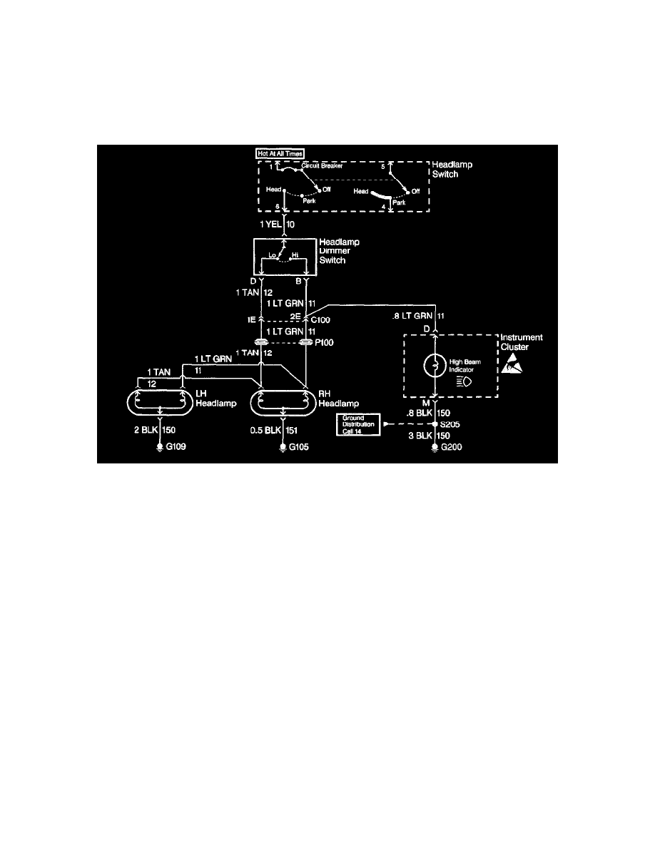
At this point analyze and (diagnose the problem), and develop text. Since the high beam indicator illuminated when the headlamp dimmer switch
was in the high position, the high contacts of the headlamp dimmer switch and the LT GRN wire between the headlamp dimmer switch and C100
are good. At this point, it is extremely unlikely that the high beam filaments in the RH and LH headlamps are both open or that both headlamp
connections are bad. The cause must be a bad connection at C100 or an open in the LT GRN wire between C100 and the RH headlamp.
Repair and Verify Fix
From isolating the root cause, basically the problem has been diagnosed. Using the Component Location Table and the corresponding figure,
quickly find C100 and the LT GRN wire, locate the exact trouble point and make the repair.
Check the thoroughness of the repair by performing a final system check on the headlamp circuit. This of course means making sure that both high
beams, both low beams, and the high beam indicator are working.
Testing For Electrical Intermittents
Perform the following procedures while wiggling the harness from side to side. Continue this at convenient points (about 6 inches apart) while watching
the test equipment.
-
Testing for Short to Ground
-
Testing for Continuity
If the fault is not identified, perform the procedure below using the MIN MAX feature on the J 39200 DMM. This feature allows you to manipulate the
circuit without having to watch the J 39200. The J 39200 will
generate an audible tone when a change is detected.
IMPORTANT: The J 39200 must be used in order to perform the following procedure since the J 39200 can monitor current, resistance or voltage
while recording the minimum (MIN), and maximum (MAX) values measured.
1. Connect the J 39200 to both sides of a suspected connector (still connected), or from one end of a suspected circuit to the other. Refer to
Troubleshooting with a Digital Multimeter See: General Electrical Diagnostic Procedures/Troubleshooting Tools/Digital Multimeterfor
information on connecting the J 39200 to the circuit.
2. Set the rotary dial of the J 39200 to the V (AC) or V (DC) position.
3. Press the range button of the J 39200 in order to select the desired voltage range.
4. Press the MIN MAX button of the J 39200. The J 39200 displays 100 ms RECORD and emits an audible tone (beep).
IMPORTANT: The 100 ms RECORD mode is the length of time an input must stay at a new value in order to record the full change.