
K 1500 Truck 4WD V6-262 4.3L (1991)
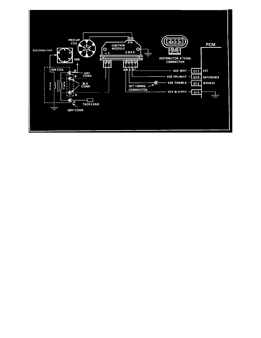
Wiring Diagram For Ignition System Check
IGNITION SYS. CHECK (SEALED MODULE CONN. DIST.)
TEST DESCRIPTION: Numbers below refer to circled numbers on the diagnostic chart.
1.
Two wires are checked, to ensure that an open is not present in a spark plug wire.
1A. If spark occurs with EST connector disconnected, pick-up coil output is too low for EST operation.
2.
A spark indicates the problem must be the distributor cap or rotor.
3.
Normally, there should be battery voltage at the "C", and "+" terminals. Low voltage would indicate an open or a high resistance circuit from the
distributor to the coil or ignition switch. If "C" terminal voltage was low, but "+" terminal voltage is 10 volts or more, circuit from "C" terminal to
ignition coil or ignition coil primary winding is open.
4.
Checks for a shorted module or grounded circuit from the ignition coil to the module. The distributor module should be turned "OFF," so normal
voltage should be about 12 volts. If the module is turned "ON," the voltage would be low, but above 1 volt. This could cause the ignition coil to fail
from excessive heat. With an open ignition coil primary winding, a small amount of voltage will leak through the module from the "Bat." to the
"tach" terminal.
5.
Applying a voltage (1.5 to 8 volts) to module terminal "P" should turn the module "ON" and the "tach" terminal voltage should drop to about 7-9
volts. This test will determine whether the module or coil is faulty or if the pick-up coil is not generating the proper signal to turn the module "ON."
This test can be performed by using a DC battery with a rating of 1.5 to 8 volts. The use of the test light is mainly to allow the "P" terminal to be
probed more easily. Some digital multi-meters can also be used to trigger the module by selecting ohms, usually the diode position. In this position
the meter may have a voltage across it's terminals which can be used to trigger the module. The voltage in the ohm's position can be checked by
using a second meter or by checking the manufacturer's specification of the tool being used.
6.
This should turn "OFF" the module and cause a spark. If no spark occurs, the fault is most likely in the ignition coil because most module problems
would have been found before this point in the procedure. A module tester could determine which is at fault.
Manifold Absolute Pressure (MAP) Output Check