
K 1500 Truck 4WD V6-262 4.3L (1991)
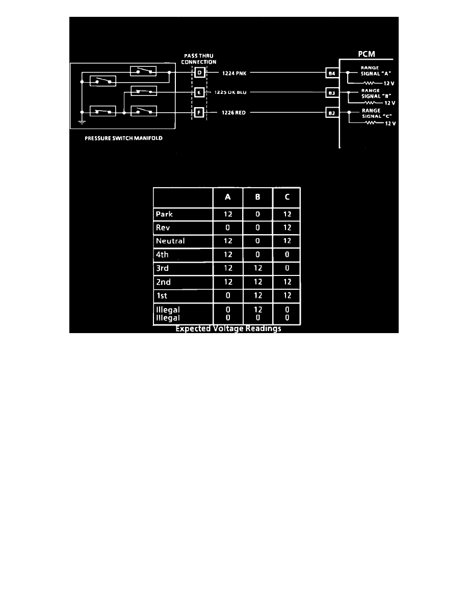
Wiring Diagram For Pressure Switch Manifold Check Procedure
PRESSURE SWITCH MANIFOLD CHECK
CIRCUIT DESCRIPTION:
The Pressure Switch Manifold (PSM) is actually five pressure switches combined into one unit and mounted on the valve body. The PCM supplies
battery voltage to the PSM on three separate wires. By grounding one or more these circuits through various combinations of the pressure switches
inside the pressure switch manifold, the PCM detects what gear range has been selected by the vehicle operator.
TEST DESCRIPTION: Numbers below refer to circled numbers on the diagnostic chart.
1.
This test compares the indicated range to the range actually selected.
2.
This test checks for correct voltage from the PCM to the transmission pass through connector.
3.
This final test will detect a short to ground in any one of the three PSM range circuits.
DIAGNOSTIC AIDS:
Code 28 will set if the PCM detects one of two illegal PSM combinations. See chart for various combinations. Be sure to check pass thru connector for
good contact.