
K 1500 Truck 4WD V6-262 4.3L VIN Z (1993)
Throttle Body: Service and Repair
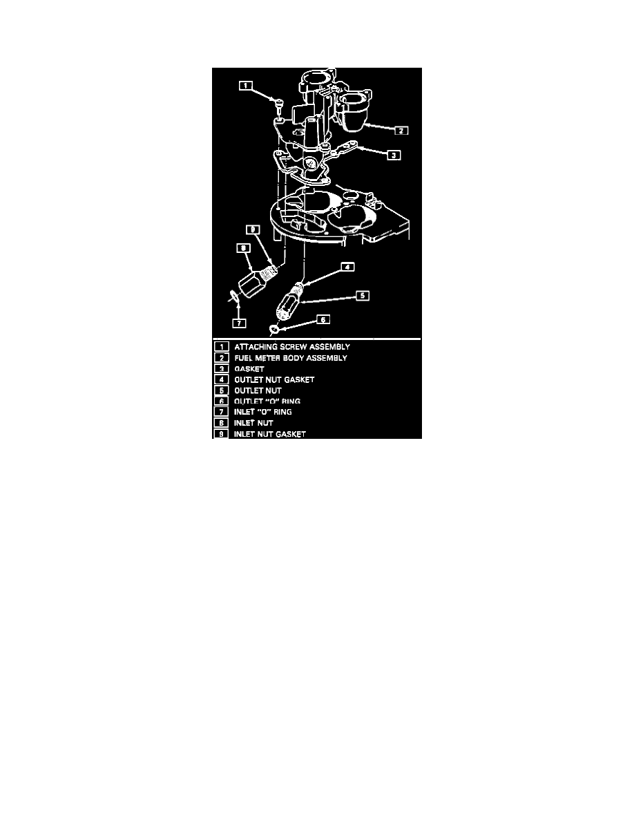
Fuel Meter Body Assembly
Fuel Meter Body Assembly
REMOVE OR DISCONNECT
1. Electrical connections to fuel injectors. (Squeeze plastic tabs and pull straight up.)
2. Fuel meter cover assembly:
Refer to FUEL METER COVER ASSEMBLY.
3. Fuel injectors:
Refer to FUEL INJECTOR ASSEMBLIES.
4. Fuel inlet and outlet lines. Discard O-rings.
5. Fuel inlet and outlet nuts and gaskets from fuel meter body assembly. Discard gaskets.
NOTE Note locations of nuts, for proper reassembly later as inlet nut has a larger passage than outlet nut.
6. Fuel meter body to throttle body attaching screw assemblies.
7. Fuel meter body assembly from throttle body assembly.
8. Throttle body to fuel meter body gasket and discard.
INSTALL OR CONNECT
1. New throttle body to fuel meter gasket. Match cut-out portions in gasket with openings in throttle body.
2. Fuel meter body assembly on throttle body assembly.
3. Fuel meter body-to-throttle body attaching screw assemblies, precoated with appropriate locking compound. Tighten screw assemblies to 4.0
Nm (35.0 lb-in).
4. Fuel inlet and outlet nuts with new gaskets to fuel body assembly. Tighten inlet nut to 40.0 Nm (30.0 lb-ft) and outlet nut to 29.0 Nm (21.0
lb-ft).
5. Fuel inlet and return lines and new O-rings. (Use back-up wrench to keep TBI nuts from turning. Tighten fuel lines to 27.0 Nm (20.0 lb-ft).
6. Injectors with new upper and lower O-rings in fuel meter body assembly.
7. Fuel meter cover gasket, fuel meter outlet gasket, and pressure regulator seal.
8. Fuel meter cover assembly.
9, Long and short fuel meter cover attaching screw assemblies, coated with appropriate compound. Tighten screw assemblies to 3.0 Nm (27.0