
K 1500 Truck 4WD V6-4.3L VIN W (1997)
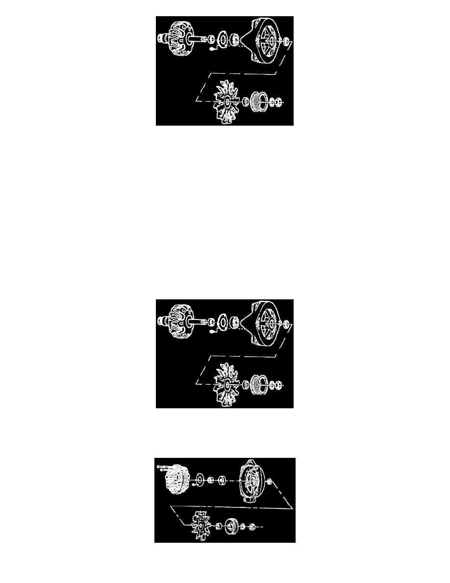
Drive End Frame Components
REMOVE OR DISCONNECT
TOOL REQUIRED:
J 28509-A Bearing Remover
-
Scribe a mark to help locate the frame end parts in the same position during assembly.
1. Four through-bolts.
2. Rotor and drive end frame assembly from the Slip Ring End (SRE) frame assembly.
NOTICE: On models with a slip ring end bail bearing on the rotor shaft, this bearing must be replaced with a new bearing any time the two
halves of the generator are separated. If not replaced, the bearing may bind and fall due to distortion of its outer tolerance rings. This does not
apply to roller-type slip ring end frame bearings.
-
Place the rotor in a vise and tighten only enough to permit removal of the pulley nut.
NOTICE: The rotor may be distorted if the vise is overtightened.
3. Nut and washer from the shaft.
4. Pulley, collar, fan, and outside collar from the shaft.
5. Drive end frame and the inside collar from the rotor shaft.
Drive End Frame Components
6. Three screws and the retainer from the drive end frame.
-
Press the bearing from the drive end frame.
CS-144 Components (Part 2 Of 2)