
K 1500 Truck 4WD V8-305 5.0L VIN M SFI (1996)
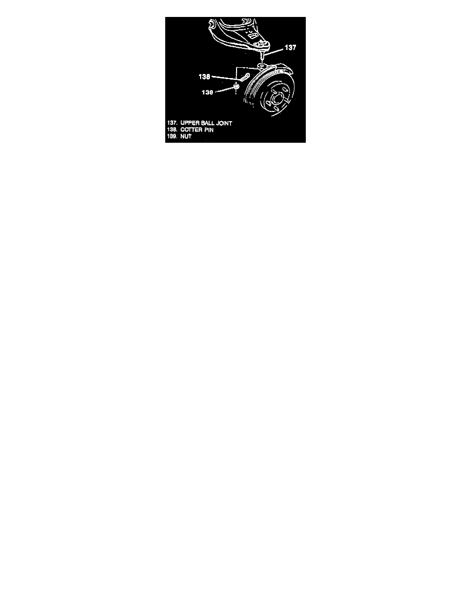
11. Nut (139).
12. Stud (137) from knuckle.
Important: Cover the shock mounting bracket and the ball stud on the lower control arm with a shop towel to prevent possible drive axle
(halfshaft) boot damage during removal and installation.
13. Knuckle assembly using hammer and brass drift or equivalent to separate outer C/V joint splined shank from knuckle hub.
14. Six bolts (200) from inboard joint flange.
-
Support inboard end of drive axle (halfshaft). Move knuckle and hub assembly outward to free splined shank from hub.
15. Drive axle (halfshaft) from vehicle.
Important: Wipe the wheel bearing seal area on the knuckle clean.
Inspect
-
Check the seal for cuts or tears.
16. Lubricate the seal lip.
-
If seal is cut or torn, inspect the wheel bearing for damage and replace the seal.
17. Replace the seal as follows:
-
Pry old seal from knuckle and discard.
-
Lubricate the new seal lip.
-
Use J 36605 to install the seal in the knuckle.
INSTALL OR CONNECT
NOTICE: Always use the correct fastener in the proper location. When you replace a fastener, use ONLY the exact part number for that application.
The manufacturer will call out those fasteners that require a replacement after removal. The manufacturer will also call out the fasteners that require
thread lockers or thread sealant. UNLESS OTHERWISE SPECIFIED, do not use supplemental coatings (paints, greases, or other corrosion inhibitors
on threaded fasteners or fastener joint interfaces. Generally, such coatings adversely affect the fastener torque and joint clamping force, and may
damage the fastener. When you install fasteners, use the correct tightening sequence and specifications. Following these instructions can help you
avoid damage to parts and systems.
-
Prior to drive axle (halfshaft) installation, cover the shock mounting bracket, lower control arm ball stud, and all other sharp edges with shop
towels so that drive axle (halfshaft) boot is not damaged during assembly.
Important: Do not lubricate the drive axle (halfshaft) splines and knuckle with grease.
1. Insert outer C/V joint splined shank into knuckle hub and secure inboard C/V joint flange to companion flange with bolts. Do not tighten.
2. Upper ball joint to the steering knuckle.
3. Stud nut.
-
Tighten stud nut to 100 Nm (75 ft. lbs.).
4. Cotter pin.
-
Lubricate the upper ball joint until grease appears at the seal.
5. Stabilizer shaft bushing (65) and bracket (64) and bolts (63).
-
Tighten bolts (63) to 33 Nm (24 ft. lbs.).
6. Stabilizer shaft link bolt assembly (62), spacer (56), and nut assembly (50).
-
Obtain torque by running nut assembly to the unthreaded portion of the bolt, then tighten to 18 Nm (13 ft. lbs.).
-
Remove floor jack or stand from beneath lower control arm.
7. Shock absorber to the lower shock mounting bracket.
8. Shock mounting bolt washer and nut.