
K 1500 Truck 4WD V8-5.7L VIN R (1997)
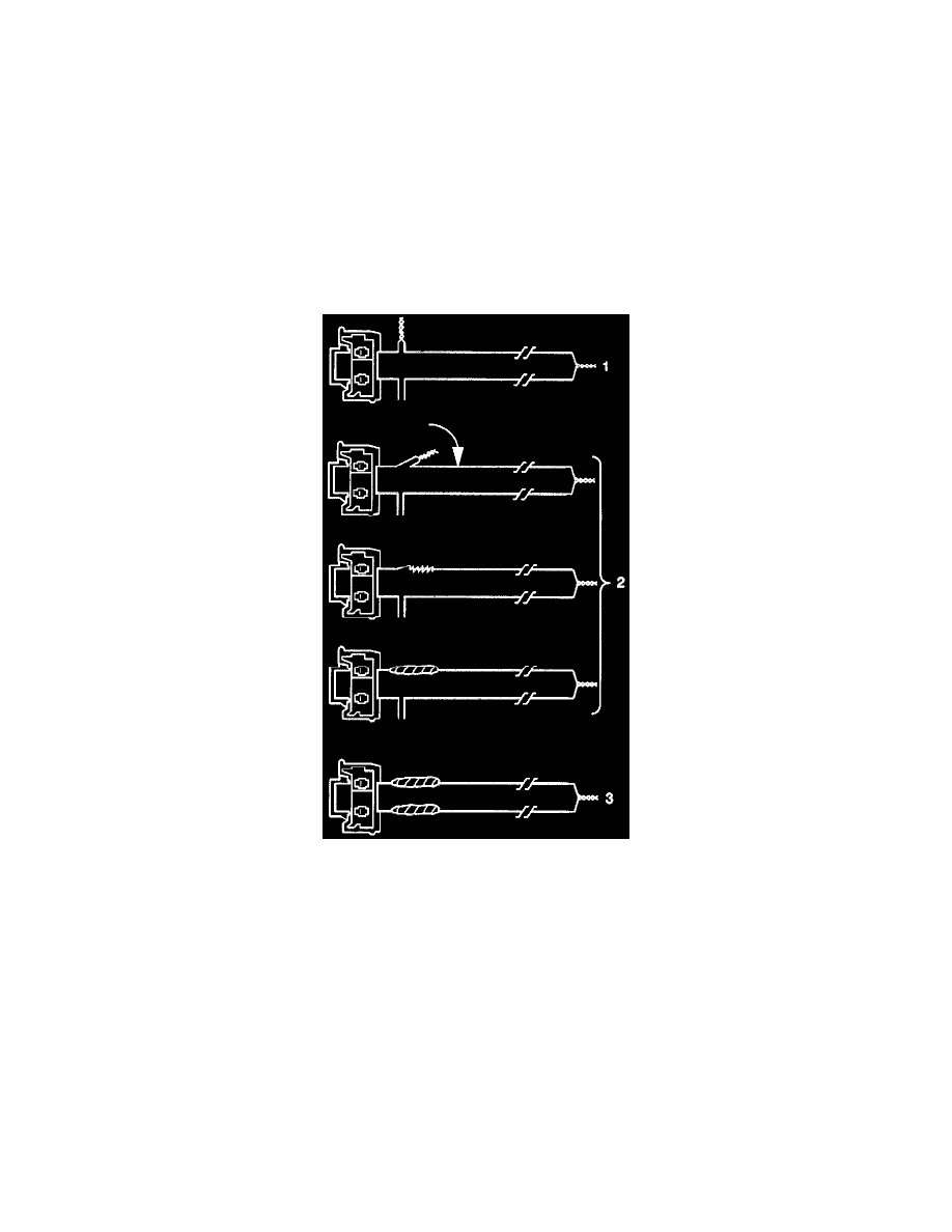
11. Twist together one connector wire lead to one deployment wire. The connection must be mechanically secure (Figure 26-1).
12. Bend flat the twisted connection that you made in the previous step. Secure the connection by wrapping tightly with electrical tape. this will also
insulate the connection (Figure 26-2).
13. Twist together, bend and tape the remaining connector wire lead to the remaining deployment wire (Figure 26-3).
14. Connect the deployment harness to the inflatable restraint steering wheel module, yellow 2-way connector at the base of the steering column.
15. Route the deployment harness out the driver side of the vehicle (Figure 27).
CAUTION: When you are deploying an inflator module for disposal, perform the deployment procedures in the order listed:
^
Wear safety glasses throughout the procedures.
^
Make sure the area around the inflator module is clear of all people and loose or flammable objects.
^
Short the deployment harness wires as instructed.
^
Connect the deployment harness to the inflator module before you connect it to the power source.
^
Connect the deployment harness to the power source to immediately deploy the air bag.
Failure to follow the procedures in the order listed may result in personal injury.
Figure 26
16. Disconnect inflatable restraint I/P module, yellow 2-way connector located behind the passenger knee bolster.
17. Cut the inflatable restraint I/P module harness connector from the vehicle. Leave at least 160 mm (6 inches) of wire at the connector (Figure 28).
18. Strip 13 mm (0.5 inch) of insulation from each wire lead of the connector (Figure 28).
19. Cut two 6.1 m (20 feet) deployment wires from 0.8 mm sq (18 gauge) or thicker multi-strand wire. Use these wires to fabricate the passenger
deployment harness (Figure 29).
20. Strip 13 mm (0.5 inch) of insulation from both ends of the wires cut in the previous Step.
21. Short the wires by twisting together one end of each (Figure 29). The deployment wires shall remain shorted and not connected to a power source
until you are ready to deployed the air bag.