
K 1500 Truck 4WD V8-6.5L DSL Turbo VIN F (1999)
Control Assembly: Description and Operation
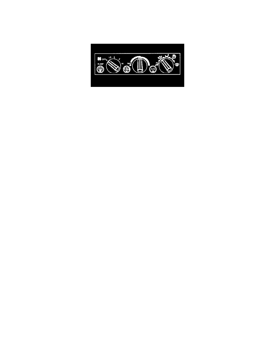
HVAC System - Manual
General Information
The air conditioning system on C/K models is electronically controlled. Three backlit, rotary knobs provide full control of the system. The rotary knobs
control the following items:
-
The blower speed
-
The air temperature
-
The mode of operation
Two push-to-latch buttons select recirculation mode for maximum cooling and control over the air conditioning compressor.
The blower speed rotary control has 4 fan speeds and an OFF position. When the blower fan is turned oft, all the HVAC operations turn off also.
The temperature rotary control has 180° of travel. A detent at the full cold-end of travel engages recirculation. Operating the system with the temperature
control placed in the detent results in maximum cooling. Air inside the passenger compartment recirculates through the blower case. Use of outside air is
minimal. Manually select recirculation by pushing the RECIRC button.
The mode rotary control has 3 major detents that indicate mode positions:
-
The vent
-
The floor
-
The defrost
Placing the control anywhere in between the major detents results in air output blending between the two modes. The recirculation mode is not available
anytime DEFROST is selected, or while air is being blended out of the defrost outlets.
Automatic recirculation occurs when the compressor head pressures exceed 2275 kPa (350 psi) and disables after the head pressures reach 1724 kPa
(250 psi). When activated, automatic recirculation cannot be manually disabled by the MAX button.
HVAC Blower Controls Circuit Description
AUXILIARY BLOWER CONTROLS (HEATER WITHOUT A/C)
CKT 341 (BRN) supplies battery voltage to relay coil cavity 5 of each of the 3 auxiliary blower relays when the ignition switch is in the RUN
position. CKT 542 (RED) supplies battery voltage to cavity 1 of each of the 3 auxiliary blower relays when the ignition switch is in the RUN
position. The relay coils are not grounded and the relays remain de-energized when the auxiliary heater control switch is in the OFF position. The
auxiliary blower motor is supplied no voltage and the relay contacts remain open.
A ground path is provided for the auxiliary low blower relay coil through CKT 1926 (DK BLU) to the control switch when the ignition switch is in
the RUN position, and the auxiliary heater control switch is in the LO position. A ground path is then provided through CKT 150 (BLK) to ground
G200. The relay coil energizes and the relay contacts close. CKT 1176 (YEL) applies battery voltage to the auxiliary blower resistor. CKT 1172
(YEL) carries a current through 2 resistors and to the auxiliary blower motor. The motor operates at the slowest speed.
The auxiliary medium blower relay is energized when the auxiliary heater control switch is in the MED position. The current flows to the motor
through 1 resistor and the motor operates at an intermediate speed. The auxiliary high blower relay is energized when the auxiliary heater control
switch is in the HI position. The current bypasses both resistors and the motor operates at the highest speed.
The auxiliary heater control switch provides an illumination lamp in order to facilitate switch operations. The lamp is powered by the instrument
panel dimming system.
The auxiliary blower motor is controlled by either of 2 auxiliary blower switches when the optional auxiliary heating and air conditioning is
provided. Both switches are located in the overhead modules. 1 switch is located in the instrument panel. The other switch is located in the center
of the vehicle. The auxiliary blower motor operates from the auxiliary blower switch. The auxiliary switch is located at the front auxiliary HVAC
control module and is in the REAR position. Refer to HVAC Air Delivery Circuit Description for a description of the control priorities for the
ventilation modes. See: Description and Operation/HVAC System - Manual/HVAC Air Delivery Circuit Description