
K 1500 Truck 4WD V8-6.5L DSL Turbo VIN F (1999)
Accessory Delay Module: Diagram Information and Instructions
Electrical Schematics
IMPORTANT: The schematic does not represent the components and wiring as they physically appear on the vehicle. For example, a 4-foot length of
wire is treated no differently in a schematic from one which is only a few inches long.
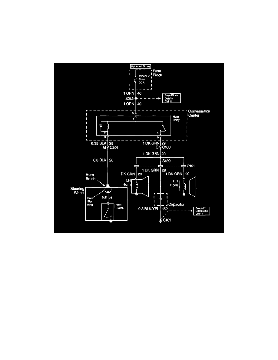
When diagnosing a horn problem use the service information located in the Horns service category. The following schematic is a typical example of a
schematic with its supporting text.
The wiring schematic is the cornerstone of electrical diagnosis. Schematics break the entire electrical system into individual circuits, showing the
electrical current paths when a circuit is operating properly. Wiring which is not part of the circuit of interest is referenced to another page where the
circuit is shown complete. Schematics use a top (power) to bottom (ground) sequence to present electrical information.
Component Location Views