
K 20 3/4 Ton Pickup 4WD V8-350 5.7L VIN L 4-bbl (1982)
Antilock Brakes / Traction Control Systems: Description and Operation
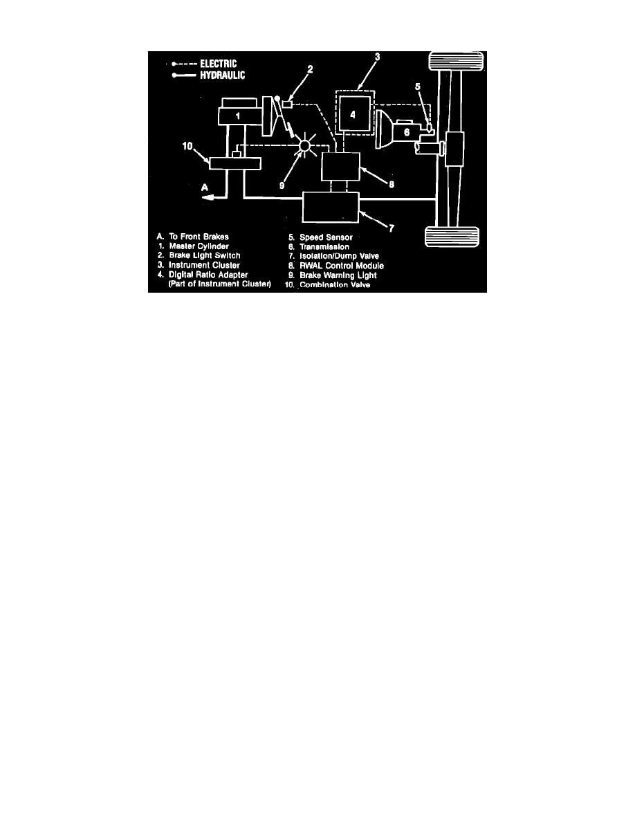
Fig. 1 Rear Wheel Anti-Lock (RWAL) system schematic
The Rear Wheel Anti-Lock (RWAL) system, Fig. 1, reduces the occurrence of rear wheel lockup during severe braking by regulating rear hydraulic
line pressure. Pressure applied to the rear wheel brakes is regulated by a control valve assembly located under the master cylinder. The control valve
consists of a dump valve which releases hydraulic pressure into an accumulator, and an isolation valve which holds rear brake pressure. Operation of the
dump valve and isolation valve is controlled by an Electronic Control Unit (ECU) which is mounted next to the master cylinder.
The ECU receives signals from the brake lamp switch and the transmission mounted speed sensor. Signals from the speed sensor are transmitted
through a digital ratio adapter mounted on the instrument cluster, and the adapter is used to calibrate the system for the specific rear axle ratio and rear
tires used on the vehicle. The ECU operates the control valves according to speed sensor and brake switch inputs, allowing maximum rear braking
while preventing rear wheel lock-up. As pressure is applied to the brake pedal during severe brake application, the ECU will control the valves to
perform one of three functions or a combination of all three. The ECU operates the valves to allow full hydraulic pressure to be applied to the rear the
rear brakes, reduces pressure applied to the rear brakes by pulsing the dump valve, or increases pressure applied to the rear brakes by pulsing the
isolation valve.
The ECU is programmed to perform a self-diagnostic function, and it stores trouble codes which relate to sensed malfunctions in the RWAL system.
The system is connected to the existing brake warning lamp. An indication of system operation and bulb check is performed through the warning lamp,
and each time the ignition is switched on the lamp will remain on for approximately 2 seconds. System malfunctions are indicated by the brake warning
lamp, and if the ECU senses a malfunction a trouble code is stored in its memory and the warning lamp will remain on whenever the ignition is on. The
procedure for determining trouble codes is outlined under Diagnosis and Testing.