
K 2500 Truck 4WD V6-262 4.3L (1988)
2. Rotor (5) and bearing (6) assembly.
^
Mark the location of the clutch coil terminals on the compressor.
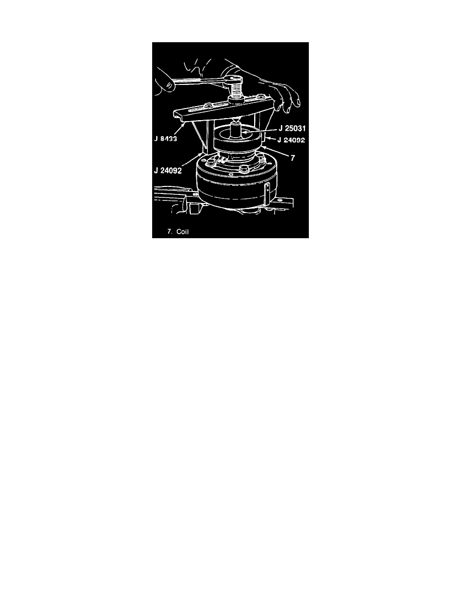
3. Clutch coil (7) from the front head (15).
^
Install J 25031 guide to the shaft (34).
^
Install J 24092 with J 8433.
^
Turn the screw in J 8433 to remove the clutch coil.
Install or Connect
1. Clutch coil (7) to the front head (15).
^
Position the coil terminals as marked during removed.
2. Rotor (5) and bearing (6) to the compressor with J 26271.
Important
^
Before seating the assembly, position the clutch coil terminals in the proper location to the compressor.
^
Align the three protrusions on the rear of the clutch coil housing with the locator holes in the front head.
3. Retainer ring (4).
Measure
^
Clutch plate to clutch rotor air gap is 0.5-1.0 mm (0.020-0.040-inch).