
K 2500 Truck 4WD V6-262 4.3L VIN Z (1992)
Brake Signal Circuit
Circuit Description:
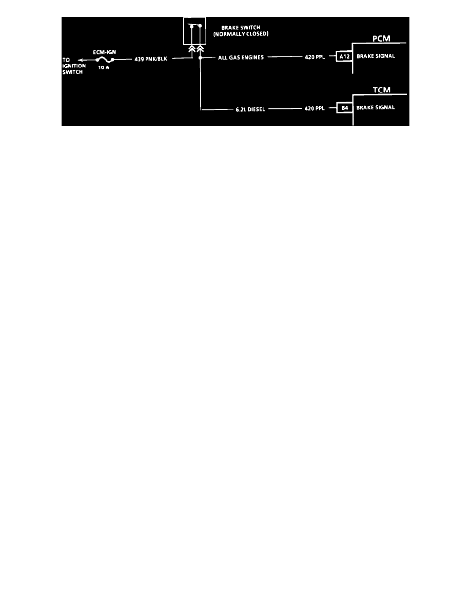
The normally closed brake switch supplies a 12 volt signal on CKT 420 to the PCM/TCM. The signal voltage is removed when the brakes are
applied. An incorrect brake signal may affect TCC operation.
Test Description:
Number(s) below refer to circled number(s) on the diagnostic chart.
1. Checks for voltage at brake switch.
2. This test simulates brake switch closed or brakes "OFF".
3. Checks CKT 420 from brake switch to PCM/TCM.
4. This opens CKT 420 and simulates brakes being applied.
Diagnostic Aids:
^
See: Powertrain Management/Computers and Control Systems/Testing and Inspection/Symptom Related Diagnostic
Procedures/Intermittent Condition
^
Check customer driving habits and/or unusual traffic conditions (i.e. stop and go expressway traffic).