
K 2500 Truck 4WD V8-305 5.0L VIN M SFI (1996)
^
Tool Required:
-
J 36607 Ball Joint Separator
-
J 36605 Steering Knuckle Seal Installer
-
Or Equivalents
REMOVAL
NOTE: Raise the vehicle and support with suitable safety stands.
Remove or disconnect the following:
1. Tire and wheel assembly.
a. Wrap shop towels around both the inner and outer ON joint boots to avoid damage to the boots during removal and installation.
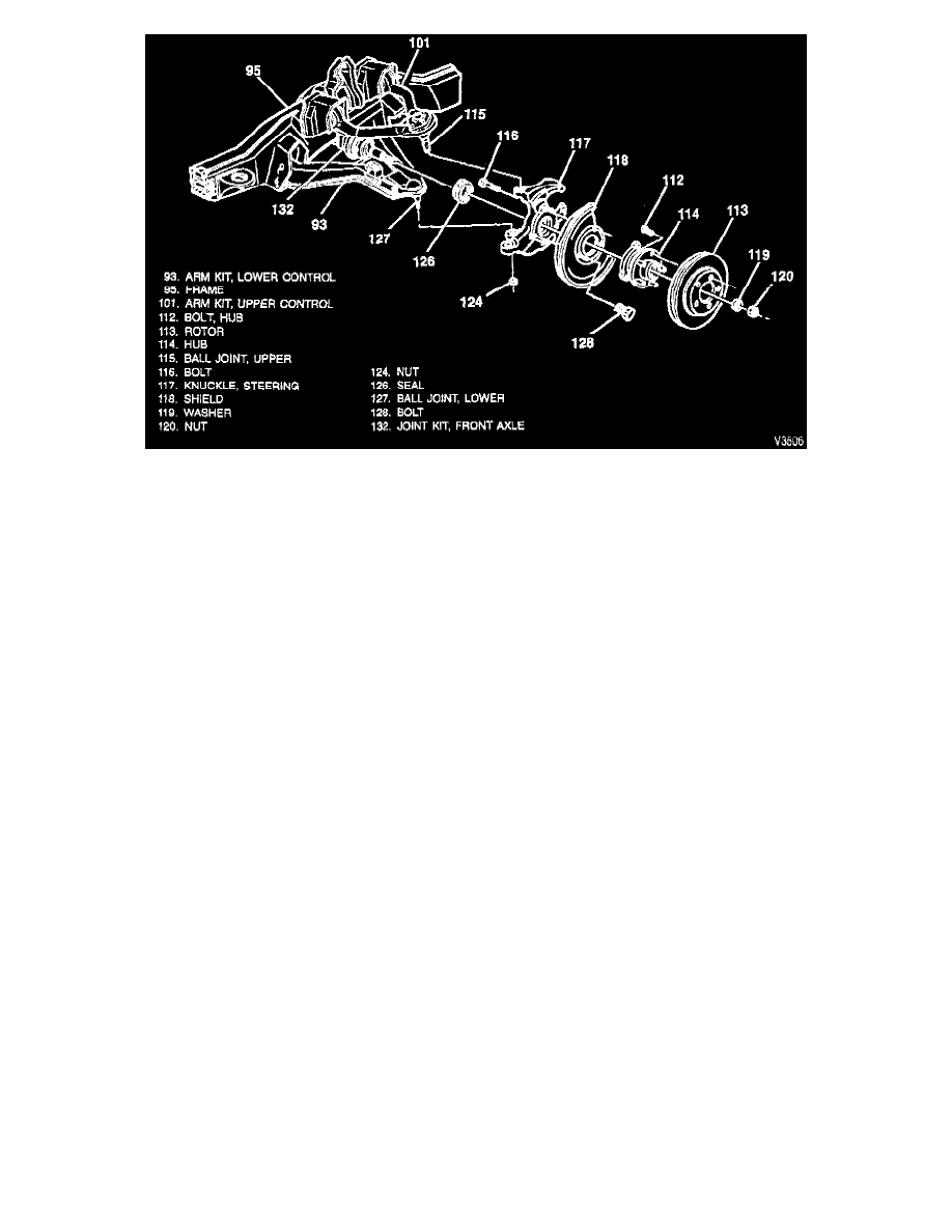
2. Brake caliper.
NOTE: Support the caliper with a piece of wire to prevent damage to the brake line.
3. Brake rotor.
4. Drive axle (halfshaft) nut (120).
5. Washer (119).
6. Tie rod nut (124).
7. Tie rod end from the knuckle (117).
8. Hub and bearing assembly (114), using a puller.
NOTE: Lay the hub and bearing assembly on the hub bolt (outboard) side. This will prevent damage or contamination of the bearing seal.
9. Drive axle (halfshaft).
10. Splash shield bolts (128).
11. Splash shield (118).
a. Support the lower control arm with a jack stand.
12. Upper ball joint nut.
13. Upper ball joint (115) from the knuckle (117). Using J 3660
7.
14. Lower ball joint nut.
15. Lower ball joint (127) from the knuckle (117). Using J 3660
7.
16. Knuckle (117).
17. Seal from the knuckle.
INSTALLATION
CAUTION: Always use the correct fastener in the proper location. When you replace a fastener, use ONLY the exact part number for that
application. The manufacturer will call out those fasteners that require a replacement after removal. The manufacturer will also call out the fasteners
that require thread lockers or thread sealant. UNLESS OTHERWISE SPECIFIED, do not use supplemental coatings (paints, greases, or other