
K 2500 Truck 4WD V8-6.5L DSL Turbo VIN F (1995)
2. Unload the torsion bar using tool J 36202. Mark the adjuster bolt for reinstallation of the torsion bar.
3. Brake hose bracket.
4. Caliper and wire oft to the side.
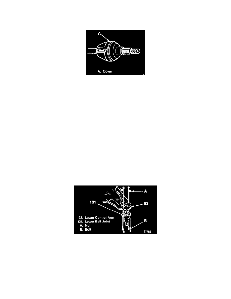
Drive Axle Cover Installed
^
Install the drive axle boot cover.
5. Outer tie rod end (125) from the knuckle using J24319-01.
6. Drive axle shaft nut (120) and washer (119) from the hub assembly.
^
Separate the shaft (132) from the splined hub (114).
7. Cotter pins (130) from upper and lower ball joint nuts.
^
Support the lower control arm assembly (93) with a jack.
8. Upper and lower ball joint nuts (129 and 131).
9. Separate the upper ball joint (115) from the knuckle (117) using J 36607.
10. Separate the lower ball joint (127) from the knuckle (117) using J 24319-01.
^
Using the support jack, remove the knuckle assembly.
11. Rivets
A. Center punch the bottom of the rivets.
B. Using a 3.175 mm (1/8-inch) drill bit, drill a guide hole 6.35 mm (1/4-inch) into the center of each rivet heads.
C. Using an 12.7 mm (1/2-inch) drill bit, drill the rivet head off.
D. Drill a hole two-thirds the length of the rivet shank, using a 8 mm (5/16-inch) drill.
E. Using an 8 mm (5/16-inch) pin punch, punch out the rivets.
TOOL REQUIRED:
J 36202 Torsion Bar Unloading Tool
INSTALL OR CONNECT
1. Ball joint (127) to the control arm.
Installing The Lower Ball Joint (Riveted / Bolted)
2. Bolts (137) and nuts (136) to the ball joint (127)
^
Tighten nuts (136) to 60 Nm (45 lbs. ft.).
^
Raise lower control arm with the hydraulic jack.
3. Knuckle to the upper ball joint.
4. Nut (131)
TIGHTEN
A. Nut to 128 Nm (94 ft.lbs.)
B. Nut must be tightened with the control arm at the "Z" height.
C. Tighten the nut to align the cotter pin. Do not tighten more than 1/6 turn.