
K 2500 Truck 4WD V8-6.6L DSL Turbo VIN 1 (2002)
3. Re-position the heater hose.
4. Install the heater outlet hose bracket nut (1).
-
Tighten the nut to 9 Nm (80 inch lbs.).
5. Install the bolt (2) retaining the heater outlet hose to the generator bracket.
-
Tighten the heater hose bracket bolt to 25 Nm (18 ft. lbs.).
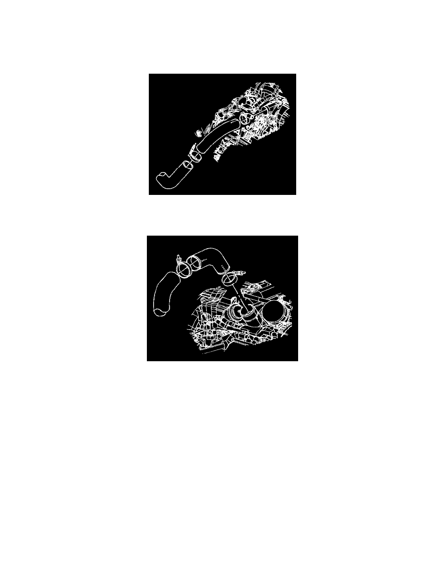
6. Install the charged air cooler inlet duct to turbocharger cool air outlet hose to the turbocharger.
7. Position the clamp as shown for proper clearance.
-
Tighten the clamp to 6 Nm (53 inch lbs.).
8. Install the charged air cooler outlet duct to intake hose.
The hose is marked DUCT, which connects to the charged air cooler outlet duct.
The hose is marked ENG, which connects to the intake manifold duct.
Align the marks on the hose with the alignment marks on the pipe and duct.
9. Position the clamps as shown for proper clearance.
-
Tighten the clamps to 6 Nm (53 inch lbs.).