
K 3500 Truck 4WD V8-454 7.4L (1994)
^
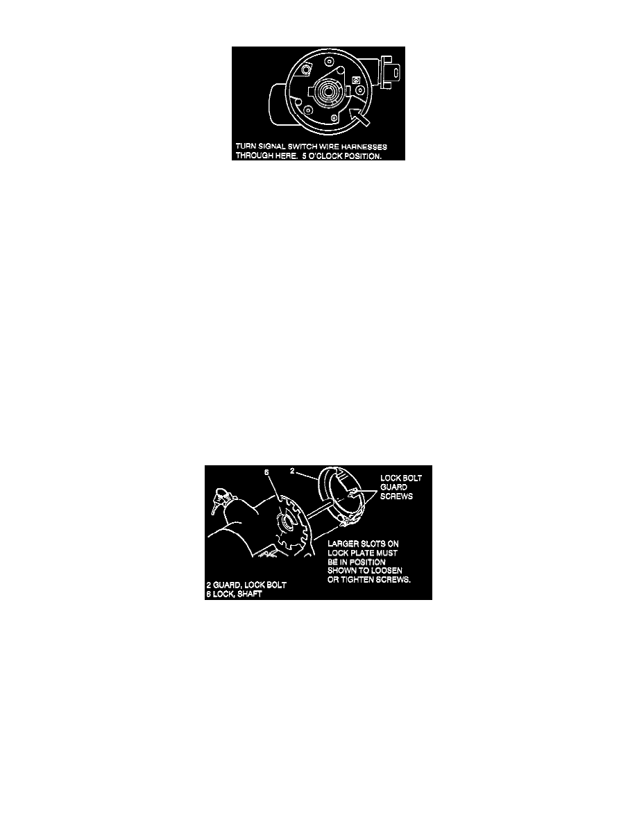
Key in "LOCK" position.
Wire Harness Through Column
6. Turn signal switch assembly (12) wire harness through steering column.
^
Let switch hang freely.
^
Switch connector to vehicle wire harness.
7. Turn signal switch assembly (12) and screws (9).
TIGHTEN
^
Tighten screws (9) to 3.4 Nm (30 lb.in.).
8. Signal switch arm (11) and screw (10).
TIGHTEN
^
Tighten screws (10) to 2.3 Nm (20 lb.in.).
9. Hazard knob assembly and multi-function lever.
10. Inner race (14).
11. Upper bearing inner race seat (13).
12. Upper bearing spring (8).
13. Turn signal cancelling cam assembly (7).
^
Lubricate with grease, synthetic (service kit).
14. Shaft lock (6).
15. New shaft lock retaining ring (5) using J 23653-C to push down shaft lock (6).
^
Ring (5) must be firmly seated in groove on shaft.
Removing Lock Bolt Guard
16. Lock bolt guard (2).
A. Place ignition switch to "RUN" position.
B. Rotate shaft (55) until block tooth is at 7 o'clock position and bolt guard screw holes are accessible through wide slots in shaft lock (6).
C. Lock bolt guard (2) and tighten screws on guard until screw heads bottom out.
TIGHTEN
^
Tighten two bolts to 2.3 Nm (20 lb.in.).
INSPECT
^
Rotate shaft lock (6).
^
Shaft lock (6) must not bind on guard screws or tabs on bolt guard (2).
NOTICE: Gently pull lower turn signal wires to remove any wire kinks that may be inside steering column assembly. Failure to do so may cause