
K 3500 Truck 4WD V8-454 7.4L VIN J SFI (1996)
ESD Symbol
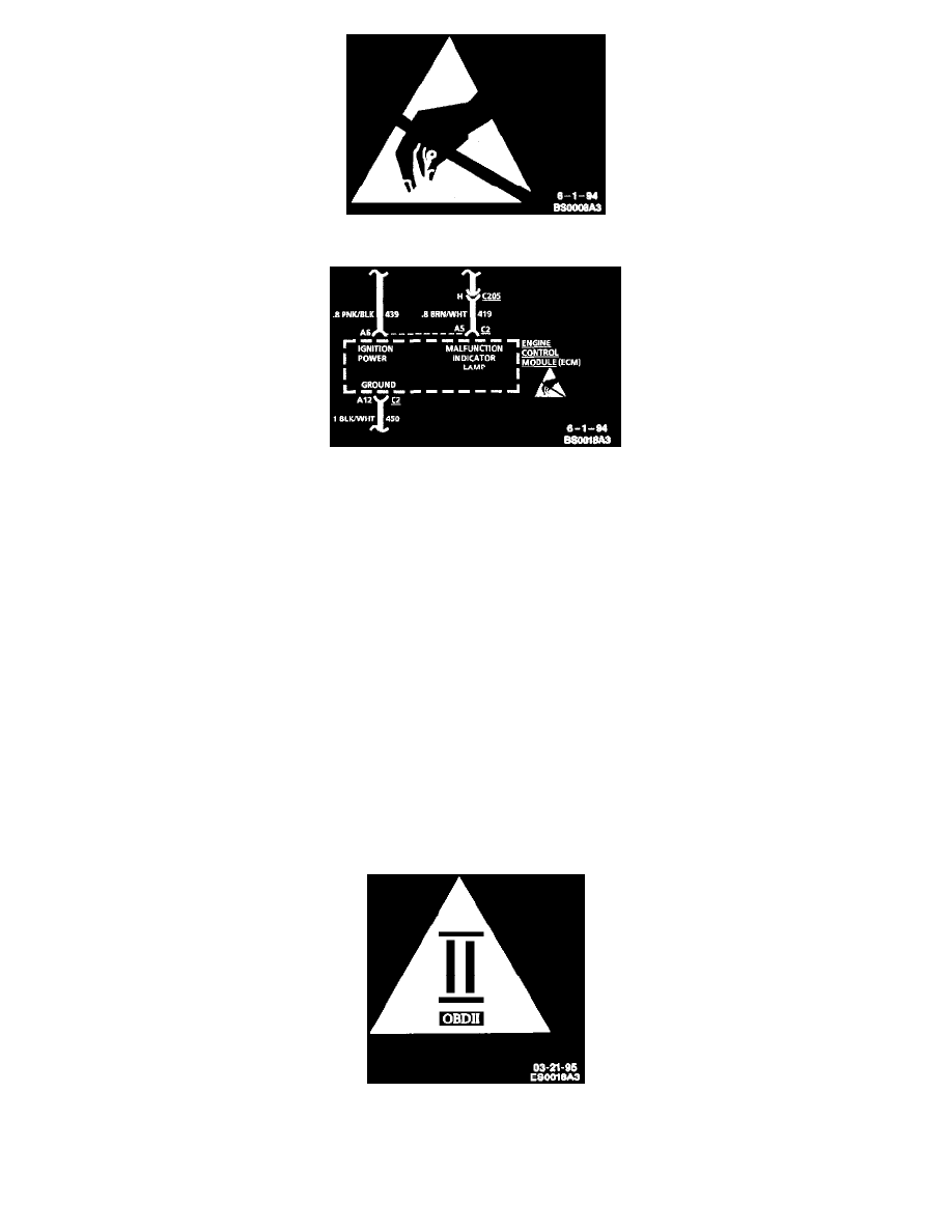
Typical Schematic
The ESD symbol is used on schematics to indicate which components are ESD sensitive. When handling any electronic part, the service technician
should follow the guidelines below to reduce any possible electrostatic charge build-up on the service technician's body and inadvertent discharge to the
electronic part. If it is not known whether or not a component is ESD sensitive, assume it is susceptible.
Handling Procedures
1. Always touch a known good ground before handling the part. This should be repeated while handling the pan and more frequently after sliding
across a seat, sitting down from a standing position or walking a distance.
2. Avoid touching electrical terminals of the part, unless so instructed by a written diagnostic procedure.
3. When using a voltmeter, be sure to connect the ground lead first.
4. Do not remove a part from its protective package until it is time to install the part.
5. Before removing the part from its package, ground the package to a known good ground on the vehicle.
Measuring Procedures
The circuits shown within the boxes are greatly simplified. Do not troubleshoot by measuring resistance at any terminal of these devices unless so
instructed by a written diagnostic procedure. Due to the simplification of the schematics, resistance measurements could be misleading, or could
lead to electrostatic discharge.
On Board Diagnostics II (OBDII) Symbol
On Board Diagnostics II (OBDII) Symbol
The OBDII symbol is used on circuit diagrams to alert the technician that the circuit is essential for proper OBDII emission control circuit operation.
Any circuit which, if it fails, causes the SERVICE ENGINE SOON indicator to turn on, is identified as an OBDII circuit.