
K Tahoe 4WD V8-4.8L VIN V (2000)
^
The Heated Oxygen Sensors (HO2S)
^
The HO2S heater
^
The EGR system
^
The AIR system
IMPORTANT: The System Status display indicates only whether or not the test has been completed. The System Status display does not necessarily
mean that the test has passed. If a Failed Last Test indication is present for a DTC associated with one of the above systems, diagnosis and repair is
necessary in order to meet the IIM requirement. Verify that the vehicle passes all of the diagnostic tests associated with the displayed System Status prior
to returning the vehicle to the customer. Refer to the Typical Drive Cycle table, more than one drive cycle may be needed, to use as a guide to complete
the I/M System Status tests.
Following a DTC info clear, System Status clears for one or all of these systems. Following a battery disconnect or a PCM replacement, all System
Status information clears.
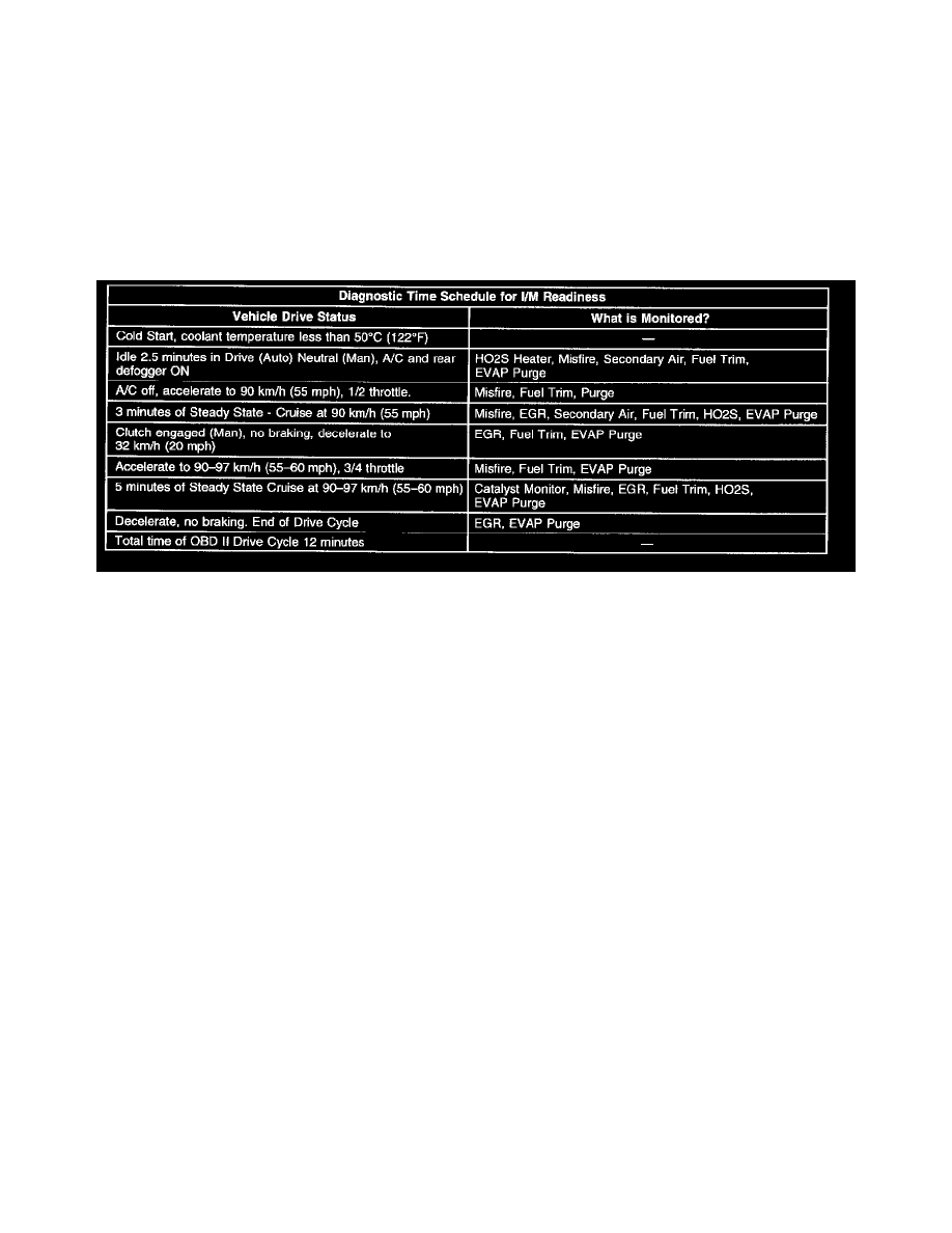
Typical Drive Cycle
Primary System Based Diagnostics
There are primary system-based diagnostics which evaluate the system operation and their effect on vehicle emissions. The primary system-based
diagnostics are listed below, with a brief description of the diagnostic functionality.
Oxygen Sensor Diagnosis
Diagnose the fuel control heated oxygen sensors for the following conditions:
^
Heater performance, time to activity on cold start
^
Slow response
^
Response time, time to switch R/L or L/R
^
Inactive signal, output steady at bias voltage - approximately 450 mV
^
Signal fixed high
^
Signal fixed low
Diagnose the catalyst monitor heated oxygen sensors for the following functions:
^
Heater performance, time to activity on cold start
^
Signal fixed low during steady state conditions
^
Inactive sensor
Heated Oxygen Sensors
The main function of the precatalyst Heated Oxygen Sensor (HO2S) is to provide the PCM with exhaust stream information in order to maintain proper
fueling to hold emissions within acceptable levels. These oxygen sensors are always located between the exhaust manifold and the catalytic converter.
After the sensor reaches the operating temperature, the sensor generates a voltage inversely proportional to the amount of oxygen present in the exhaust
gases.
The PCM uses the signal voltage from the fuel control heated oxygen sensors in a Closed Loop in order to adjust the fuel injector pulse width. While in a
Closed Loop, the PCM can adjust fuel delivery in order to maintain an air to fuel ratio which allows the best combination of emission control and
driveability.
If the oxygen sensor pigtail wiring, connector, or terminal are damaged, replace the entire oxygen sensor assembly. Do not attempt to repair the wiring,
the connector, or the terminals. In order for the sensor to function properly, the sensor must have a clean air reference provided to it. This clean air
reference is obtained by way of the oxygen sensor wires. Any attempt to repair the wires, connectors, or terminals could result in the obstruction of the