
K Tahoe 4WD V8-4.8L VIN V (2000)
Diagnostic Chart (Part 2 Of 2)
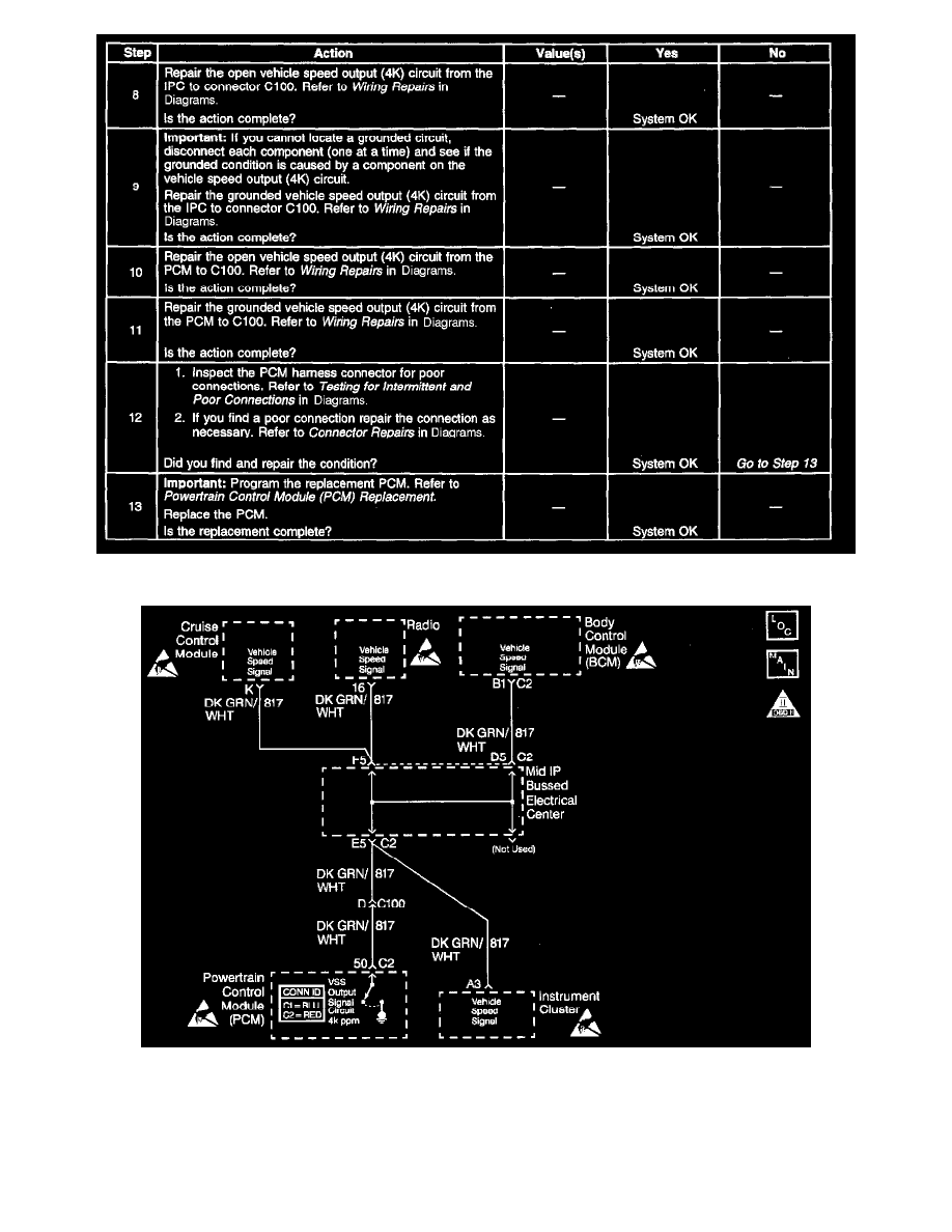
Schematic
CIRCUIT DESCRIPTION
Various components apply a voltage to the vehicle speed output circuit. The Powertrain Control Module (PCM) creates the vehicle speed output
signal by rapidly grounding this circuit via an internal switch called a driver. The driver operates at the same rate as the Vehicle Speed Sensor (VSS)
signal input. The various components recognize the voltage being pulled to ground as an indication of vehicle speed.