
K Tahoe 4WD V8-4.8L VIN V (2000)
1. Remove the component in question.
2. Visually inspect each side of the connector for signs of contamination. Avoid touching either side of the connector as oil from your skin may be a
source of contamination as well.
3. Visually inspect the terminal bearing surfaces of the flat wire circuits for splits, cracks, or other imperfections that could cause poor terminal
contact. Visually inspect the component side connector to ensure that all of the terminals are uniform and free of damage or deformation.
4. Insert the appropriate adapter from the J 42675 Flat Wire Probe Adapter Kit on the flat wire harness connector in order to test the circuit in
question.
Measuring Frequency
NOTE: Refer to Test Probe Notice in Service Precautions.
The following procedure determines the frequency of a signal.
IMPORTANT: Connecting the DMM to the circuit before pressing the Hz button will allow the DMM to autorange to an appropriate range.
1. Apply power to the circuit.
2. Set the rotary dial of the DMM to the V (AC) position.
3. Connect the positive lead of the DMM to the circuit to be tested.
4. Connect the negative lead of the DMM to a good ground.
5. Press the Hz button on the DMM.
6. The DMM will display the frequency measured.
Measuring Voltage
NOTE: Refer to Test Probe Notice in Service Precautions.
The following procedure measures the voltage at a selected point in a circuit.
1. Disconnect the electrical harness connector for the circuit being tested, if necessary.
2. Enable the circuit and/or system being tested. Use the following methods:
-
Turn ON the ignition, with the engine OFF.
-
Turn ON the engine.
-
Turn ON the circuit and/or system with a scan tool in Output Controls.
-
Turn ON the switch for the circuit and/or system being tested.
3. Select the V (AC) or V (DC) position on the DMM.
4. Connect the positive lead of the DMM to the point of the circuit to be tested.
5. Connect the negative lead of the DMM to a good ground.
6. The DMM displays the voltage measured at that point.
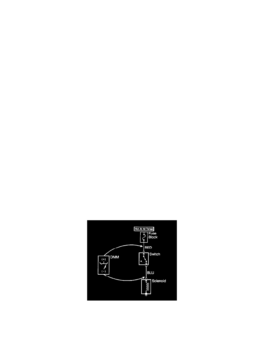
Measuring Voltage Drop
NOTE: Refer to Test Probe Notice in Service Precautions.
The following procedure determines the difference in voltage potential between two points.
1. Set the rotary dial of the DMM to the V (DC) position.
2. Connect the positive lead of the DMM to one point of the circuit to be tested.
3. Connect the negative lead of the DMM to the other point of the circuit.
4. Operate the circuit.
5. The DMM displays the difference in voltage between the two points.