
Lumina V6-191 3.1L (1990)
2.
Install lock cylinder and torque retaining retaining screw to 27 inch lbs.
3.
Install alarm assembly by pushing down into retaining bore until bottomed with plastic tab covering lock retaining screw.
4.
Lubricate bearing with lithium grease and press into housing with a 1 1/2 inch socket until bottomed.
5.
Install housing spacer and column housing and torque screw to 88 inch lbs.
6.
Turn lock cylinder to the Run position and insert steering shaft into the lower end of jacket and bowl assembly until shaft rests against bearing.
The shaft will extend 2 1/2 inches beyond the highest surface of column housing when installed properly.
7.
Install thrust washer, upper bearing spring and thrust washer.
8.
Wrap a two inch wide piece of shim stock .005 inch, around the shaft and slip a new retaining ring up to the thrust washer. Use two long handled
screwdrivers and push on retaining ring until it seats in the retainer ring groove in shaft. Discard shim stock.
9.
Install adapter and lower bearing assembly and torque adapter screws to 27 inch lbs.
10.
Install lower bearing seat and lower bearing spring.
11.
Install two new lower spring retainers and compress spring until retainers are positioned 1.14 inch from lower end of steering shaft.
12.
Perform assembly steps for turn signal cancel cam assembly, pivot & pulse switch assembly & turn signal switch assembly as previously
described.
IGNITION & DIMMER SWITCH ASSEMBLY
Disassembly
1.
Place shift lever in the Park position and lock cylinder in the Off position.
2.
Remove steering column from vehicle.
3.
Disconnect turn signal switch and pivot and pulse switch connectors from ignition and dimmer switch assembly connector.
4.
Remove bowl shield screw and nut and remove bowl shield.
5.
Remove dimmer and ignition switch assembly as follows:
a. Remove dimmer switch nut, upper mounting stud, then dimmer switch.
b. Remove lower mounting stud and ignition switch from ignition switch actuator rod.
6.
Remove dimmer switch actuator rod from rod cap.
Assembly
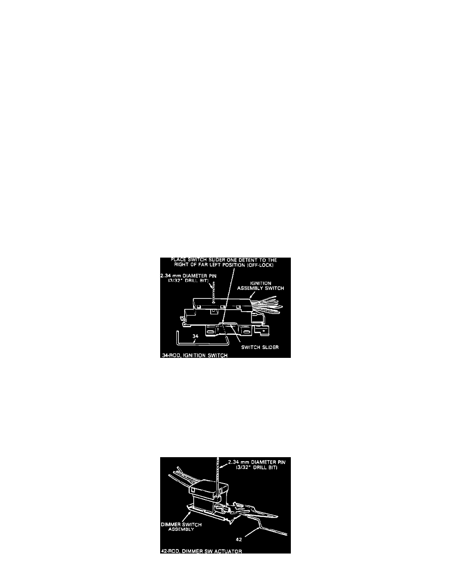
Fig. 89 Installing Ignition Switch & Actuator
1.
Place the ignition switch slider in the far left position and move back one detent to the right, Off-Lock position. Fig. 89.
2.
Insert a 3/32 inch drill bit into the adjustment hole on ignition switch to hold switch slider in proper position during installation.
3.
Install ignition switch to switch rod.
4.
Install ignition switch to jacket and bowl assembly with lower mounting stud and torque stud to 35 inch lbs.
5.
Remove drill bit from ignition switch and install dimmer switch actuator rod, tab first, through hole in instrument panel bracket and hole in dimmer
switch rod cap.
6.
Tab on rod must engage wide slot in rod cap and snap in place.
7.
Install dimmer switch onto actuator rod and dimmer switch assembly on lower mounting stud with dimmer switch nut and upper mounting stud.