
Lumina V6-191 3.1L VIN T MFI (1993)
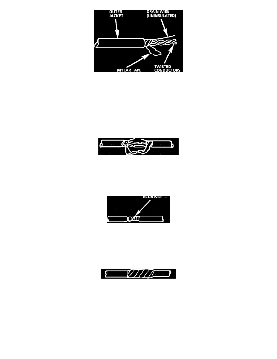
Fig. 15 Twisted/Shielded Cable
Twisted/shielded cable is sometimes used to protect wiring from electrical noise (stray signals). For example, two-conductor cable of this construction is
used between the ECM and the distributor. See Fig. 15 for a breakdown of twisted/shielded cable construction.
Step 1: Remove Outer Jacket
Remove the outer jacket and discard it. Be careful to avoid cutting into the drain wire or the mylar tape.
Step 2: Unwrap the Tape
Unwrap the aluminum/mylar tape, but do not remove it. The tape will be used to rewrap the twisted conductors after the splices have been
made.
Step 3: Prepare the Splice
Fig. 16 The Untwisted Conductors
Untwist the conductors. Then, prepare the splice by following the splicing instructions for copper wire presented earlier. Remember to stagger
splices to avoid shorts, Fig. 16.
Step 4: Re-assemble the Cable
Fig. 17 The Re-assembled Cable
After you have spliced and taped each wire, rewrap the conductors with the mylar tape. Be careful to avoid wrapping the drain wire in the tape.
Next, splice the drain wire following the splicing instructions for copper wire. Then, wrap the drain wire around the conductors and mylar tape,
Fig. 17.
Step 5: Tape the Cable
Fig. 18 Proper Taping
Tape over the entire cable using a winding motion, Fig. 18. This tape will replace the section of the jacket you removed to make the repair.
Repairing Connectors
The following general repair procedures can be used to repair most types of connectors. The repair procedures are divided into three general groups:
Push-to-Seat and Pull-to-Seat and Weather Pack.
^
See CONNECTOR TERMINAL I.D. to determine which type of connector is to be serviced.
^
Use the proper Pick(s) or Tool(s) that apply to the terminal.
^
The GM Terminal Repair Kit (J 38125-A) contains further information.