
Lumina V6-191 3.1L VIN T MFI (1993)
6.
Install pinion and valve assembly with spool shaft retaining ring and valve body rings installed into housing using clear pinion and valve assembly
ring protector tool No. 37090 to prevent ring damage.
7.
Install pinion and valve assembly onto rack using clear pinion and valve assembly ring protector tool No. J 37090 and pinion seal installer tool No.
J 29822. Do not hammer or use excessive force.
8.
Ensure notch in stub shaft and first mark on housing are lined up while rack is centered in housing. Refer to measurement ``A'' taken during
disassembly.
9.
Hold valve stub shaft and thread hex locknut into pinion, then torque to 26 ft lbs. If stub shaft is not held, damage to pinion teeth will result.
10.
Install dust cover onto housing.
11.
Install stub shaft bearing annulus assembly onto valve stub shaft.
12.
Place seal protector, tool No. J 29810 onto valve stub shaft, then apply a small quantity of grease between stub shaft seals.
13.
Install stub shaft seal and stub shaft dust seal over protector and into housing.
14.
Install retaining ring into groove in housing.
15.
Lubricate stub shaft and dust seal area, then coat rack bearing, adjuster spring and adjuster plug with lithium grease and install in housing.
16.
With rack centered in housing, turn adjuster plug clockwise until it bottoms in housing, then back off 50° to 70°. Check torque on pinion.
Maximum pinion preload torque is 16 inch lbs.
17.
Install adjuster plug locknut to adjuster plug, then tighten firmly against housing while holding adjuster plug stationary.
18.
Install rack and pinion assembly, then flush power steering system.
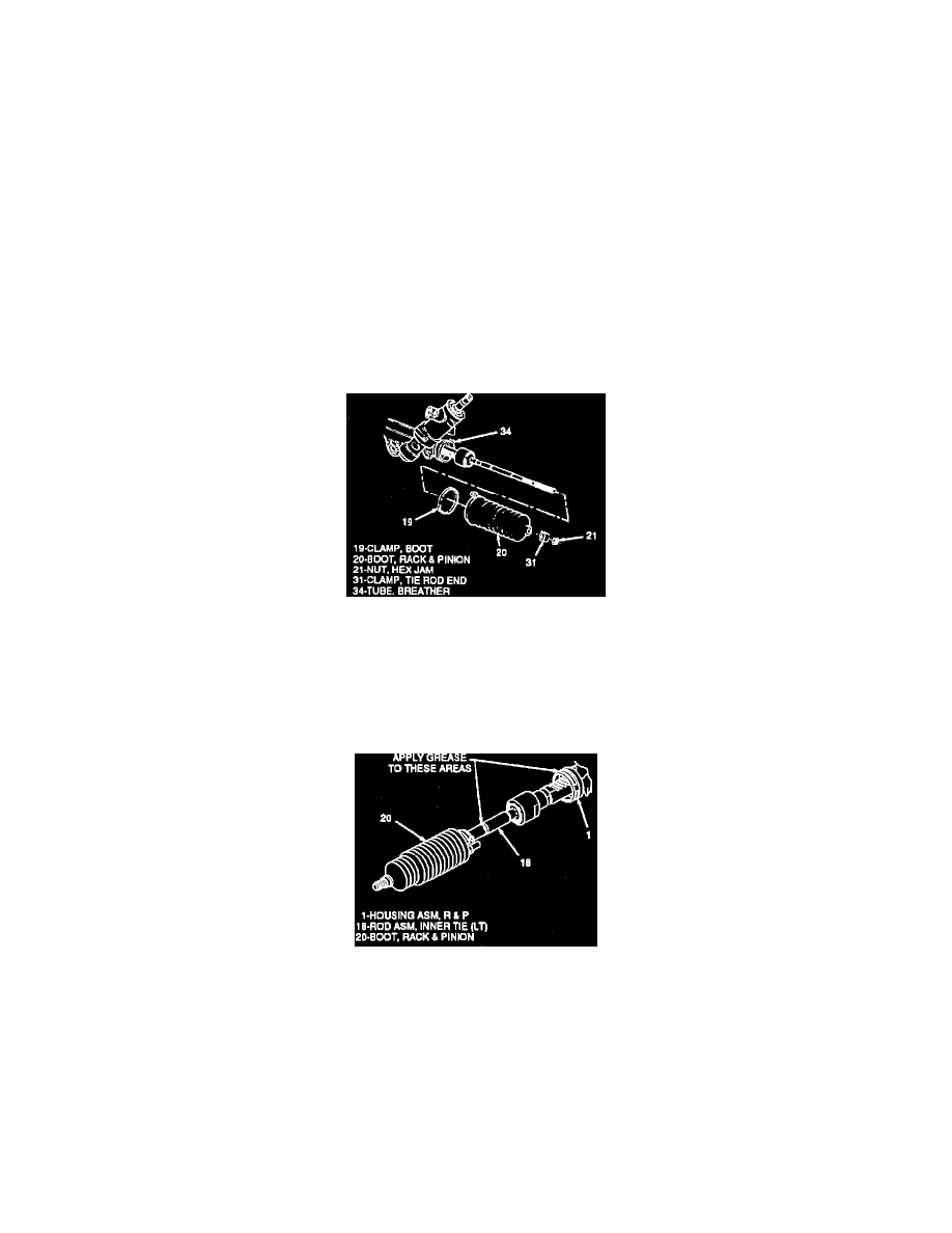
Rack & Pinion Boot & Breather Tube
Fig. 3 Boot Replacement
Removal
1.
Remove outer tie rod.
2.
Remove hex jam nut from inner tie rod assembly.
3.
Remove tie rod end clamp, Fig. 3, then boot clamp with side cutters and discard.
4.
Mark location of breather tube on housing before removing tube, then remove boot and breather tube.
Fig. 4 Boot Seal Application
Installation
1.
Install new boot clamp onto boot.
2.
Apply grease to inner tie rod or housing as shown in Fig. 4.
3.
Align and install breather tube.
4.
Install boot onto housing until seated in housing groove thang.
5.
Position boot clamp on boot and crimp.
6.
Position tie rod end clamp with pliers on boot.