
Lumina V6-204 3.4L DOHC (1991)
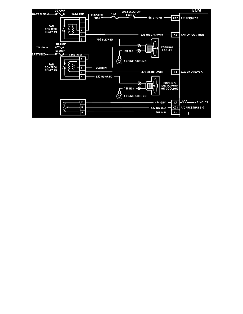
Cooling Fan Wiring Diagram
TEST DESCRIPTION:Numbers below refer to circled numbers on the diagnostic chart.
1.
12 volts should be available to circuit 250 and circuit 2 on each relay when the ignition is "ON."
2.
This test checks the ability of the ECM to ground circuit 335 (circuit 473). The "SERVICE ENGINE SOON" light should be flashing at this point.
If it isn't flashing see CHART A-2.
3.
If the fan does not turn "ON" at this point, circuit 702 (535) or circuit 150 is open, or the cooling fan motors are faulty.
System Diagnosis
Primary Cooling Fan Does Not Run
1.
With ignition switch in RUN position, ground terminal B (WHT/BLK) of the ALDL connector. If coolant fan runs, problem is ECM related.
2.
If coolant fan does not run, ground terminal A9 (DK GRN/WHT) at the ECM with a fused jumper. If coolant fan runs, problem is ECM related.
3.
If coolant fan does not run, ignition switch in RUN position, leave jumper from step 2 installed and disconnect coolant fan relay connector.
Measure voltage between terminal 3 (RED) and ground. If zero volts is present, check red wire for an open.
4.
If battery voltage is present, ensure ignition switch in RUN position, measure voltage between terminal 3 (RED) and terminal 1 (DK GRN/WHT).
If zero volts is present, check 335 (DK GRN/WHT) for an open.
5.
If battery voltage is present, disconnect primary coolant fan relay then measure voltage from terminal 2 (RED) (VIN X) or 2 (BRN/WHT) (VIN T,
VIN R) to ground at RH electrical center. If zero volts is present, check 650 (BRN/WHT) or 1444 (RED) for open.
6.
If battery voltage is present, with primary coolant fan relay disconnected connect a fused jumper with 20 amp fuse between terminals 3 (RED) and
5 (BLK/RED) at RH electrical center. If coolant fan runs, check terminal contact between primary cooling fan relay and RH electrical center, if
good, replace primary coolant fan relay.
7.
If primary coolant fan does not run, leave jumper installed from step 6 then disconnect the primary coolant fan connector and measure voltage
between terminal B (BLK/RED) and ground. If zero volts is present, check 702 (BLK/RED) wire for an open.
8.
If battery voltage is present, measure voltage between terminals B (BLK/RED) and A (BLK). If zero volts is present, check 150 (BLK) wire for an
open.
9.
If battery voltage is present, check primary cooling fan connector, if good, replace primary coolant fan.
Secondary Cooling Fan Does Not Run
1.
Turn ignition switch to RUN position, ground terminal A3 (DK BLU/WHT) at ECM with fused jumper. If cooling fan runs, problem is ECM
related.
2.
If cooling fan does not run, disconnect secondary cooling fan relay, leave fused jumper at ECM, ensure ignition switch in RUN position, then
measure voltage at RH electrical center terminal 2 (BRN) to ground. If zero volts, check 250 (BRN) wire for open.
3.
If battery voltage is present, leave ignition switch in RUN position and fused jumper at ECM, then measure voltage between terminals 2 (BRN)
and 1 (DK BLU/WHT). If zero volts, check 473 (DK BLU/WHT) wire for open.
4.
If battery voltage is present, measure voltage between terminal 3 (RED) and ground. If zero volts, check 1442 (RED) wire for open.