
Lumina V6-204 3.4L DOHC VIN X SFI (1996)
Camshaft Position Sensor: Description and Operation
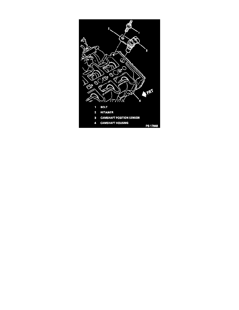
Camshaft Position Sensor
DESCRIPTION
The camshaft position sensor is located on the top of the cylinder head towards #6 cylinder. A 3-wire harness connector plugs into the sensor, connecting
it to the Powertrain Control Module (PCM). The Sensor sends a cam signal to the PCM which uses it as a sync pulse to trigger the injectors in proper
sequence. The CAM signal is passed through the ignition control module. It is filtered and buffered by the ignition control module, but the signal is not
processed in any other way. The PCM uses the CAM signal to indicate the position of the #1 piston during its power stroke. This allows the PCM to
calculate true Sequential Fuel Injection (SFI) mode of operation.
OPERATION
The PCM applies a signal voltage to the camshaft position sensor. The left bank exhaust camshaft has a tooth machined on the casting. The camshaft
position sensor is separated from the exhaust camshaft by an air gap. As the exhaust camshaft rotates, the machined tooth aligns with the camshaft
position sensor. The signal voltage to the sensor is pulled low. The PCM interprets the change in signal voltage as an indication of camshaft position.
The CAM signal is created as piston #1 is on the intake stroke. If the correct CAM signal is not received by the PCM, DTC PO341 will be set.
If the CAM signal is lost while the engine is running, the fuel injection system will shift to a calculated sequential fuel injection mode based on the last
fuel injection pulse, and the engine will continue to run. The engine can be restarted and will run in the calculated sequential mode as long as the fault is
present with a 1 in 6 chance of injector sequence being correct.