Lumina V6-204 3.4L DOHC VIN X SFI (1996)

Ignition Control Module: Description and Operation
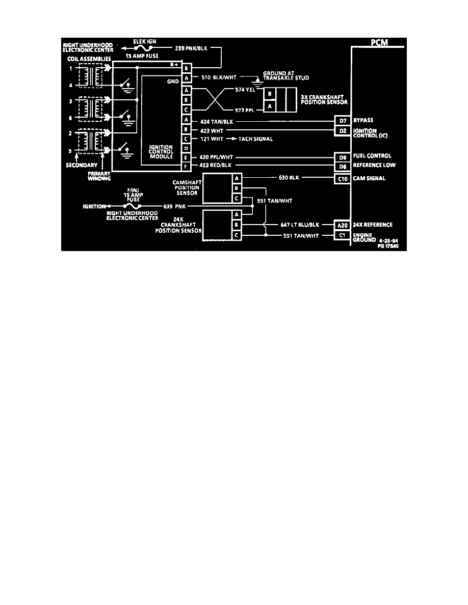
Ignition System
DESCRIPTION
The ignition control module performs several functions:
-
It determines the correct ignition coil wiring sequence, based on the sequence of 7X crankshaft position sensor pulses. This coil sequencing occurs
at start-up. After the engine is running, the module remembers the sequence, and continues triggering the ignition coils in proper sequence.
-
It determines whether or not the crankshaft is rotating in the proper direction, and cuts off fuel delivery and spark to prevent backfiring if reverse
rotation is detected.
-
It sends the 3X reference signals to the PCM. The PCM determines engine RPM from this signal. It is also used by the PCM to determine
crankshaft position for Ignition Control (IC) spark advance calculations. The falling edge of each fuel control signal pulse occurs 70 before TDC
of any cylinder. The 3X reference signal sent to the PCM by the ignition control module is an ON-OFF pulse occurring 3 times per crankshaft
revolution. The ICM calculates the 3X reference signal from the 7X crankshaft position sensor.
3X REFERENCE PCM INPUT
From the ignition control module, the PCM uses this signal to calculate engine RPM and crankshaft position at engine speeds above 1200 RPM. The
PCM also uses the pulses on this circuit to initiate injector pulses. If the PCM receives no pulses on this circuit, DTC P1374 will set and the PCM will
use the 24X reference signal circuit for fuel and ignition control. The engine will continue to start and run using the 24X reference signal only.
24X REFERENCE PCM INPUT
From the ignition control module, the PCM uses this signal to calculate engine RPM and crankshaft position at engine speeds below 1200 RPM. The
PCM also uses the pulses on this circuit to initiate injector pulses. If the PCM receives no pulses on this circuit, DTC P0336 will set and the PCM will
use the 3X reference signal circuit at all times for fuel and ignition control. The engine will continue to start and run using the 3X reference signal only.
REFERENCE LOW
This is a ground circuit for the digital RPM counter inside the PCM, but the wire is connected to engine ground only through the ignition control module.
Although this circuit is electrically connected to the PCM, it is not connected to ground at the PCM. The PCM compares voltage pulses on the 24X and
3X reference input circuits to any on this circuit, ignoring pulses that appear on both. If the circuit is open, or connected to ground at the PCM, it may
cause poor engine performance and possibly a MIL with no DTC set.
