Lumina V6-3.1L VIN J (2000)

Control Assembly: Description and Operation
Control Assembly (C60)
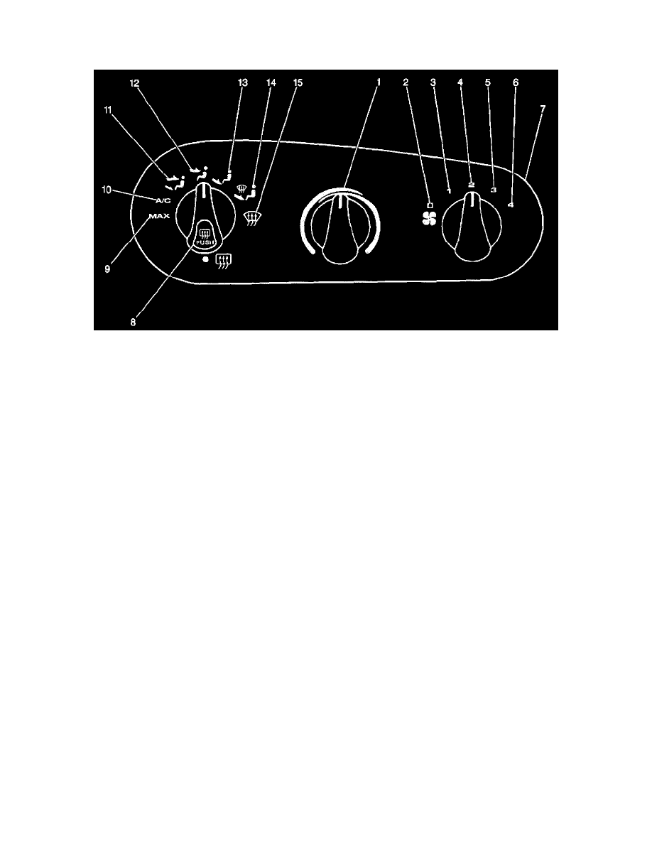
The knobs on the control head (7) control the operation of the A/C system. The compressor clutch and the blower connect electrically to the control head
by a wiring harness. Off (2) is on the blower switch. Cooled and dehumidified air is available in the Max (9), A/C (10), Bi-level (11), Defog (8) and
Defrost (15) modes.
The rotary temperature knob (1) controls the temperature valve through a potentiometer in the control and electric motor attached to the heater module.
A rotary knob (9), which sends the appropriate electrical signal to the five solenoid valves that control the flow of the vacuum on the various vacuum
valve positioning actuators, controls the modes of operation. A rotary knob, located on the control head (7), control the following blower speeds in all
modes:
^
Off (2)
^
Low (3)
^
Medium 1 (4)
^
Medium 2 (5)
^
High (6)
The temperature valve position is independent of mode selection.
For a description of the RPO Code(s) shown in this article/image, refer to the RPO Code List found at Vehicle/Application ID. See: Application and ID
