
Lumina V6-3.1L VIN J (2000)
Case: Service and Repair
Case Cover
Removal Procedure
^
Tools Required
-
J28467-A Engine Support Fixture
-
J28467-90 Engine Support Adapter
-
J36462 Engine Support Adapter Leg Set
1. Disconnect the battery ground (negative) cable. Refer to Battery Negative Cable Disconnect/Connect Procedure in Starting and Charging.
2. Remove the throttle body air inlet duct. Refer to Air Cleaner Assembly Replacement in Powertrain Management.
3. Install the J28467-A.
4. Install the J28467-90.
5. Install the J36462.
6. Remove the engine mount struts. Refer to Engine Mount Strut Replacement (Left) and Engine Mount Strut Replacement (Right) in Engine.
7. Raise and support the vehicle. Refer to Vehicle Lifting.
8. Remove the left front wheel.
9. Remove the left engine splash shield.
10. Remove the stabilizer shaft brackets from the lower control arms. Refer to Stabilizer Shaft Replacement in Steering and Suspension.
11. Remove the left tie rod end from the steering knuckle. Refer to Steering Knuckle with Strut Replacement in Steering and Suspension.
12. Remove the wheel speed sensor harness connector. Refer to Wheel Speed Sensor Jumper Hamess Replacement (Front) in Brakes and Traction
Control.
13. Remove the left lower ball joint from the left lower control arm. Refer to Steering Knuckle with Strut Replacement in Steering and Suspension.
14. Disconnect the left drive axle from the transaxle. Refer to Wheel Drive Shafts Replacement.
15. Secure the drive axle to the steering knuckle/strut.
Caution: Failure to disconnect the intermediate shaft from the rack and pinion stub shaft can result damage to the steering gear and/or
damage to the intermediate shaft. This damage may cause loss of steering control which could result in personal injury.
16. Disconnect the intermediate shaft from the steering gear. Refer to Intermediate Steering Shaft Replacement in Steering and Suspension.
17. Disconnect the three-way catalytic converter pipe to the right (rear) exhaust manifold. Refer to Catalytic Converter Replacement in Exhaust
Systems.
18. Support the right side of the frame with jackstands.
19. Support the left side of the frame with jackstands.
20. Remove the transaxle mount bracket. Refer to Automatic Transmission Mount Bracket Replacement.
21. Remove the transaxle mount. Refer to Automatic Transmission Mount Replacement.
22. Remove the engine mount lower nuts. Refer to Engine Mount Replacement in Engine.
23. Adjust the jackstand to the lower left side of the frame.
24. Loosen the right side frame to body bolts.
25. Remove the left side frame to body bolts.
26. Position the drain pan under the transaxle.
27. Remove the wiring harness connector.
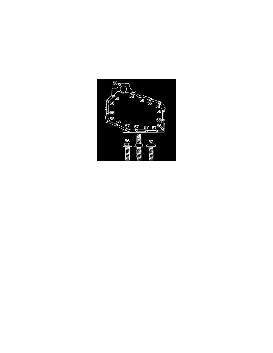
28. Remove the case side cover bolts (56-58).