
Lumina V6-3.8L VIN K (1998)
Crankshaft Position Sensor: Description and Operation
Crankshaft Position Sensor
Description
DESCRIPTION
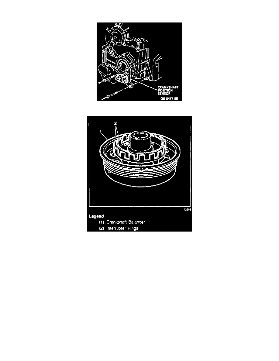
The dual Crankshaft Position Sensor (CKP) is secured in an aluminum mounting bracket and bolted to the front left side of the engine timing chain
cover, partially behind the crankshaft balancer. A 4-wire harness connector plugs into the sensor, connecting it to the ignition control module. The
dual crankshaft position sensor contains two Hall-effect switches with one shared magnet mounted between them. The magnet and each Hall-effect
switch are separated by an air gap. A Hall-effect switch reacts like a solid state switch, grounding a low current signal voltage when a magnetic field is
present.
OPERATION
Interrupter Rings
When the magnetic field is shielded from the switch by a piece of steel placed in the air gap between the magnet and the switch, the signal voltage
is not grounded. If the piece of steel (called an interrupter) is repeatedly moved in and out of the air gap, the signal voltage will appear to go ON -
OFF - ON - OFF - ON - OFF. In the case of the electronic ignition system, the piece of steel is two concentric interrupter rings mounted to the rear
of the crankshaft balancer.
Ignition Sequencing
Each interrupter ring has blades and windows that either block the magnetic field or allow it to close one of the Hall effect switches. The outer
Hall effect switch produces a signal called the CKP 18X because the outer interrupter ring has 18 evenly spaced blades and windows. The CKP
18X portion of the crankshaft position sensor produces 18 ON - OFF pulses per crankshaft revolution. The Hall-effect switch closest to the
crankshaft, the CKP Sync portion of the sensor, produces a signal that approximates the inside interrupter ring. The inside interrupter ring has 3