
Lumina V6-3.8L VIN K (1998)
3. Inspect the rotor windings with a digital multimeter.
^
The rotor windings should not be grounded (1).
^
The rotor windings should not be an open circuit (2).
^
The resistance (2) should be between 2.1-2.4 ohms at room temperature.
Replace the rotor if the windings are grounded, open or have incorrect resistance. Refer to step 16 in Disassembly Procedure.
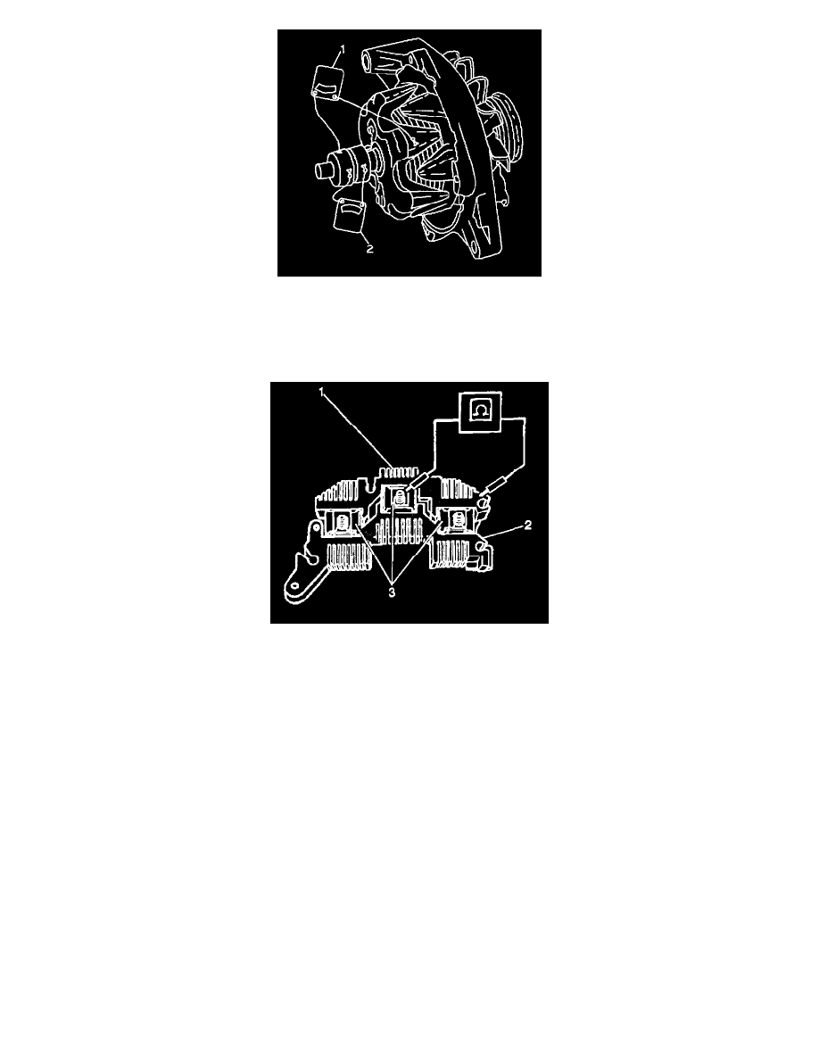
4. Inspect the slip ring end assembly.
4.1. Inspect the diodes in the rectifier bridge with a digital multimeter.
4.1.1. There should be continuity in one direction between each of the 3 phase clips (3) and the grounded heat sink (1). When the polarity of
the digital multimeter is reversed, all 3 readings should show open circuits.
4.1.2. There should be continuity in one direction between each of the 3 phase clips (1) and the positive heat sink. When the polarity of the
digital multimeter is reversed, all 3 readings should show open circuits. Replace the rectifier bridge when one or more of the readings
do not follow this pattern. Refer to step 14 in Disassembly Procedure.
4.2. Inspect the slip ring end bearing. Replace the bearing if the bearing is dry or damaged.
4.3. Inspect the brush holder assembly.
4.3.1. Replace the brush holder assembly it the brushes are damaged or broken. Replace the brush holder assembly if the brushes are worn to
less than 10 mm (0.4 in) in length. Refer to steps 7 through 11 in Disassembly Procedure.
4.3.2. Replace the brush springs if the springs are damaged or broken.
4.4. Replace the voltage regulator if no other problems are found that can cause an existing high, low or no output condition. Refer to step 13 in
Disassembly Procedure.
Assembly Procedure