
Lumina V6-3.8L VIN K (1998)
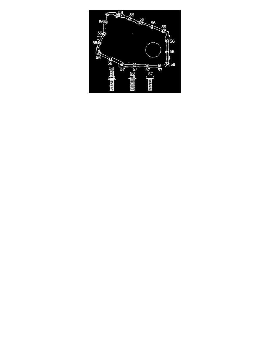
3. Install the case side cover bolts (56, 57 and 58).
^
Tighten the case side cover bolts (56, 57 and 58) to 24 Nm (17 ft. lbs.).
NOTICE: Refer to Fastener Notice in Service Precautions.
4. Remove the drain pan from under the transaxle.
5. Adjust the jackstand to raise the left side of the frame.
6. Install the left side frame to body bolts.
7. Install the right side frame to body bolts.
8. Install the engine mount lower nuts. Refer to Engine Mount Replacement.
9. Install the transaxle mount. Refer to AT Mount Replacement
10. Install the transaxle mount bracket. Refer to AT Mount Bracket Replacement.
11. Remove the jackstand support from the right side of the frame.
12. Remove the jackstand support from the left side of the frame.
13. Connect the three-way catalytic converter pipe to the right (rear) exhaust manifold. Refer to Catalytic Converter Replacement (3100 L82 (VIN M))
in Powertrain Management.
CAUTION: When Installing the Intermediate shaft make sure that the shaft is seated prior to pinch bolt Installation. If the pinch bolt is
inserted into the coupling before shaft installation, the two mating shafts may disengage. Disengagement of the two mating shafts will
cause loss of steering control which could result in personal injury.
14. Install the intermediate shaft to the steering gear. Refer to Steering Wheel and Column On-Vehicle Service.
15. Install the pinch bolt at the intermediate steering shaft. Refer to Steering Wheel and Column On-Vehicle Service.
16. Install the left drive axle to the transaxle. Refer to Wheel Drive Shafts Replacement in Drive Axle.
17. Connect the left lower ball joint to the steering knuckle. Refer to Steering Knuckle with Strut Replacement in Front Suspension.
18. Connect the wheel speed sensor wiring harness connector. Refer to Powertrain Management.
19. Install the left tie rod end to the steering knuckle. Refer to Steering Knuckle with Strut Replacement in Front Suspension.
20. Install the stabilizer shaft brackets to the lower control arms. Refer to Stabilizer Shaft Link Replacement (Stabilizer Shaft Link) in Front
Suspension.
21. Install the left engine splash shield.
22. Install the left front wheel. Refer to Wheel Installation in Wheels and Tires.
23. Lower the vehicle.
24. Install the engine mount struts. Refer to Engine Mount Strut Replacement (Left) and Engine Mount Strut Replacement (Right).
25. Remove the J 36462.
26. Remove the J 28467-90.
27. Remove the J 28467-A.
28. Remove the throttle body air inlet duct. Refer to Powertrain Management.
29. Connect the battery ground (negative) cable. Refer to Battery Negative Cable Disconnect/Connect in Starting and Charging.
NOTICE: Do NOT overfill the transaxle. The overfilling of the transaxle causes foaming, loss of fluid, shift complaints, and possible damage to
the transaxle.
30. Adjust the fluid level.
31. Inspect for proper completion of the repairs.
32. Inspect for fluid leaks.
4T65-E Automatic Transaxle
REMOVAL PROCEDURE