
Lumina V6-3100 3.1L VIN M SFI (1995)
Engine Control Module: Description and Operation
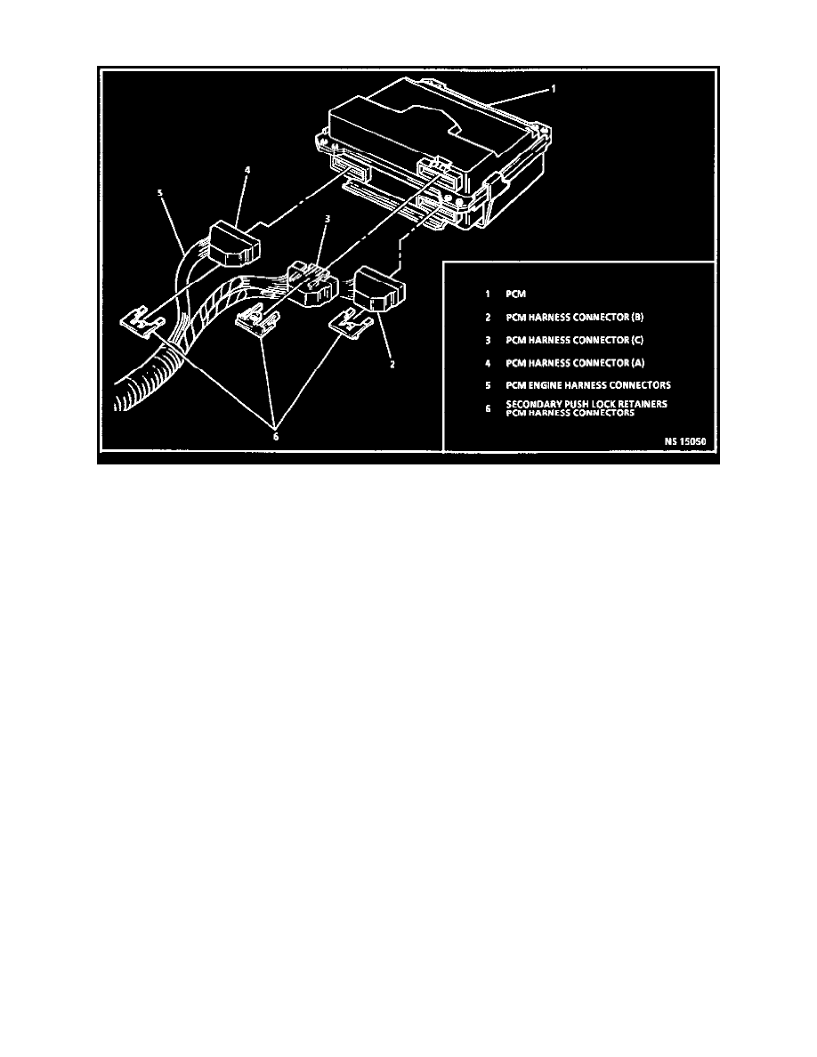
PCM
DESCRIPTION
The Powertrain Control Module (PCM), is located under the passenger side of the dash. It is the control center of the fuel injection system and
constantly looks at the information from various sensors and controls the systems that affect vehicle performance. The PCM also performs the
diagnostic function of the system. It can recognize operational problems, alert the driver through the Malfunction Indicator Lamp (MIL) "Service
Engine Soon," and store a Diagnostic Trouble Code (DTC) which identifies the problem areas to aid the technician in making repairs.
The PCM used with this engine is referred to as SFI-66. For service, this PCM consists of two parts: a dual processor controller and an electronic
Knock Sensor (KS) module.
OPERATION
The PCM contains a power supply which regulates the 12 volts vehicle supply input to 5 and 12 volts, and these voltages are used for various
internal and external functions.
The PCM supplies a buffered 5 or 12 volts to power various sensors or switches. This is done through resistances in the PCM which are so high in
value that a test light will not light when connected to the circuit In some cases, even an ordinary shop voltmeter will not give an accurate reading
because its resistance is too low. Therefore, the use of a 10 megohm input impedance digital volt meter or a Tech 1 scan tool is necessary to assure
accurate voltage readings.
The Input / Output (I/0) devices in the PCM include analog to digital converters, signal buffers, counters and special drivers. The PCM controls
output circuits such as the fuel injectors, Idle Air Control (IAC) valve, cooling fan relays, etc. by controlling the ground circuit through transistors
or a device called a "quad-driver" in the PCM.
MEMORY
There are two types of memory storage within the PCM: EEPROM and RAM.
EEPROM
Electrically Erasable Programmable Read Only Memory (EEPROM) is a permanent memory that is physically soldered to the circuit boards
within the PCM. The EEPROM contains the overall control algorithms. The EEPROM can be reprogrammed by using the Tech 1 scan tool or
other Techline "T" series terminals / !equipment.
RAM
Random Access Memory (RAM) is the microprocessor "scratch-pad" The processor can write into or read from this memory as needed. This
memory is volatile and needs a constant supply of voltage to be retained. If the voltage is lost, the memory is lost and the PCM logs a DTC 16
indicating this loss.