
Lumina V6-3100 3.1L VIN M SFI (1995)
3. Transaxle bracket. Refer to "Transaxle Support Assembly".
Auxiliary Valve Body, Valve Body & Oil Pump Assembly
AUXILIARY VALVE BODY, VALVE BODY & OIL PUMP ASSEMBLY
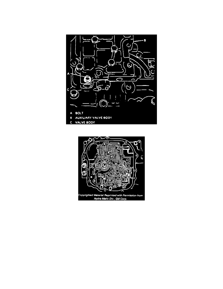
Fig. 8 Valve Body Bolt Location
Fig. 9 Check Ball Locations
1. Disconnect battery ground cable, then the TV cable.
2. Raise and support vehicle.
3. Remove left front wheel and tire assembly.
4. Remove valve body cover retaining bolts and the cover.
5. Remove TCC solenoid retaining bolt and the solenoid. Disconnect TCC solenoid and 3rd gear pressure switch electrical connectors.
6. Remove bolt securing linkage/bracket to valve body, then remove TV linkage.
7. Remove remaining valve body retaining bolts, then the valve body and six check balls. Do not remove the bolts marked A, Fig. 8, at this time.
8. Remove bolt A and separate auxiliary valve body from the valve body.
9. Remove oil pump drive rod, auxiliary valve body and cover.
10. Remove oil pump assembly.
11. Reverse procedure to install noting the following:
a. Tighten bolts in a clockwise pattern, starting from center.
b. Refer to Fig. 9 for check ball locations.
c. Adjust TV cable and fluid level.