
Lumina APV V6-191 3.1L (1990)
CLEANING/INSPECTION
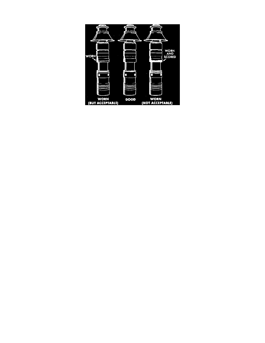
Fig. 4 Spool valve inspection
1.
Clean all parts in a suitable solvent being careful to avoid losing small parts.
2.
Inspect valve spool and valve spool bore in booster housing for corrosion, nicks, scoring or other damage. Discoloration of the spool or bore,
particularly in the grooves, is not harmful.
3.
If the valve spool or the spool bore has nicks or scoring that can be felt with a fingernail, particularly on the hands, the spool and housing should
be replaced as an assembly, Fig. 4. The clearance between the valve spool and the spool bore of the housing is important. Because of this,
the spool and housing make are made as a selective assembly and therefore can only be replaced as an assembly.
4.
Inspect the input rod and piston assembly for corrosion, nicks, scoring or excessive wear. If the piston is damaged, the input rod and piston
assembly should be replaced.
5.
Inspect piston bore in booster housing for corrosion, nicks, scoring or other damage. If the bore is damaged, the valve spool and housing should be
replaced as an assembly.
ASSEMBLY
Lubricate all the seals and metal friction points with power steering fluid.
1.
Install return line seal, then the fitting Fig. 3.
2.
Install accumulator valve and spool valve into housing.
3.
Install seal on piston assembly using seal protector tool No. J-25083 or equivalent.
4.
Install seal onto the housing, then install cover and bolts. Torque housing bolts to 22 ft. lbs.
5.
Install bracket and nut, then torque to 110 ft. lbs.
6.
Install boot, output pushrod, baffle, piston return spring, and retainer using seal protector tool No. 24551 or equivalent.
7.
Install retainer, spring, O-ring, and plug, using accumulator compressor tool No. J-26889 or equivalent, and C-clamp.
8.
Depress the accumulator, then install the retainer and remove C-clamp.
9.
Jam nut from the repair kit onto pedal rod, and install eyelet onto pedal rod.
10.
Adjust eyelet to required length.
Hydro-Boost II Assembly
DISASSEMBLY/ASSEMBLY