
Lumina APV V6-191 3.1L (1990)
Lifter / Lash Adjuster: Description and Operation
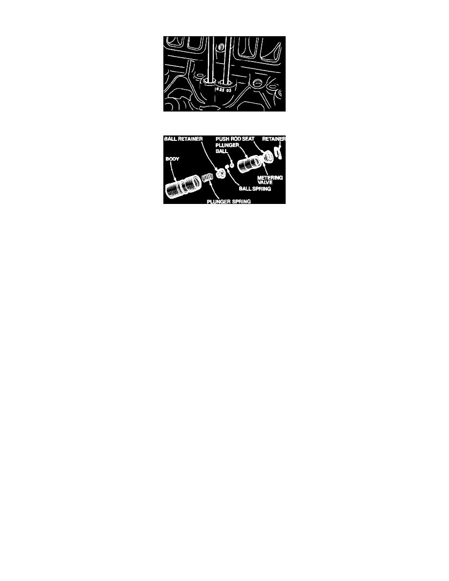
Fig. 5 Oversize Valve Lifter Marking
Fig. 6 Hydraulic Valve Lifter
Some engines will be equipped with both standard and .25 mm oversize valve lifters. The cylinder case will be marked where the oversize valve lifters
are installed with a daub of white paint and .25 mm O.S. will be stamped on the valve lifter boss, Fig. 5.
Failure of a hydraulic valve lifter, Fig. 6, is generally caused by an inadequate oil supply or dirt. An air leak at the intake side of the oil pump or too
much oil in the engine will cause air bubbles in the oil supply to the lifters causing them to collapse. This is a probable cause of trouble if several lifters
fail to function, but air in oil is an unlikely cause of failure of a single unit.
Valve lifters can be removed after removing rocker arm covers, intake manifold, rocker arm nuts, rocker arm balls, rocker arms and pushrods.