
Lumina APV V6-191 3.1L (1990)
REMOVE OR DISCONNECT
1. Negative battery cable.
2. Cruise control vacuum hoses at servo.
3. Transaxle neutral start switch connector.
4. Raise vehicle and suitably support.
5. Left front wheel and tire assembly.
6. Inner splash shield.
7. Tie rod end from knuckle assembly.
8. Stabilizer shaft link from lower control arm.
9. Ball joint from steering knuckle.
NOTICE: Drive axle seal protector J 34754 should be modified and installed on any drive axle prior to service procedures on or near the drive axle.
Failure to observe this can result in seal damage and possible joint failure.
10. Drive axle from transaxle.
11. Pinch bolt from steering gear intermediate shaft.
CAUTION: Failure to disconnect the intermediate shaft from the rack and pinion steering gear stub shaft can result in damage to the
steering gear and/or intermediate shaft. This damage may cause loss of steering control which could result in an accident and possible
personal injury.
12. Intermediate shaft from steering gear.
13. Position a transmission jack under transaxle oil pan. Raise jack until it supports transaxle.
14. Four frame-to-body bolts.
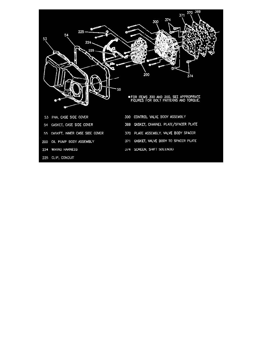
15. Lower the transmission jack and transaxle to gain access to the case side cover.
16. Oil cooler pipes at case.
17. Side cover bolts.
18. Case side cover.
CLEAN
^
Case and side cover gasket surfaces
INSTALL OR CONNECT