
Lumina APV V6-191 3.1L VIN D TBI (1995)
Neutral Safety Switch: Customer Interest
Power Door Locks - Cycle When Brake Pedal is Depressed
File In Section: 8 - Chassis/Body Electrical
Bulletin No.: 63-81-07
Date: April, 1996
Subject:
Power Door Locks Cycle When Brake Pedal is Depressed
(Replace Park/Neutral Switch, Add Connector Kit)
Models:
1995 Chevrolet Lumina Minivan
1995 Pontiac Trans Sport
with 3-Speed Transaxle Only and 3.1L Engine (VIN D - RPO LG6)
Condition
Some owners may comment that the power door locks cycle when the brake pedal is depressed. The condition may be intermittent and may occur most
often after driving through salt spray.
Cause
The park/neutral switch, on the 3-speed transaxle only (used with the 3.1L engine, VIN D) may allow water to enter, causing an internal short. This short
can cause the automatic lock function to operate when the brake switch is activated, rather than when the transaxle is moved into reverse or drive, as
designed.
Correction
The above condition was corrected with the use of a new switch for the 1996 model year. Replace the switch with the new 1996 part number. This will
also require replacement of the connector, terminals, and seals contained in a connector kit. The terminals will be indexed differently than the 1995
switch. See the instructions below.
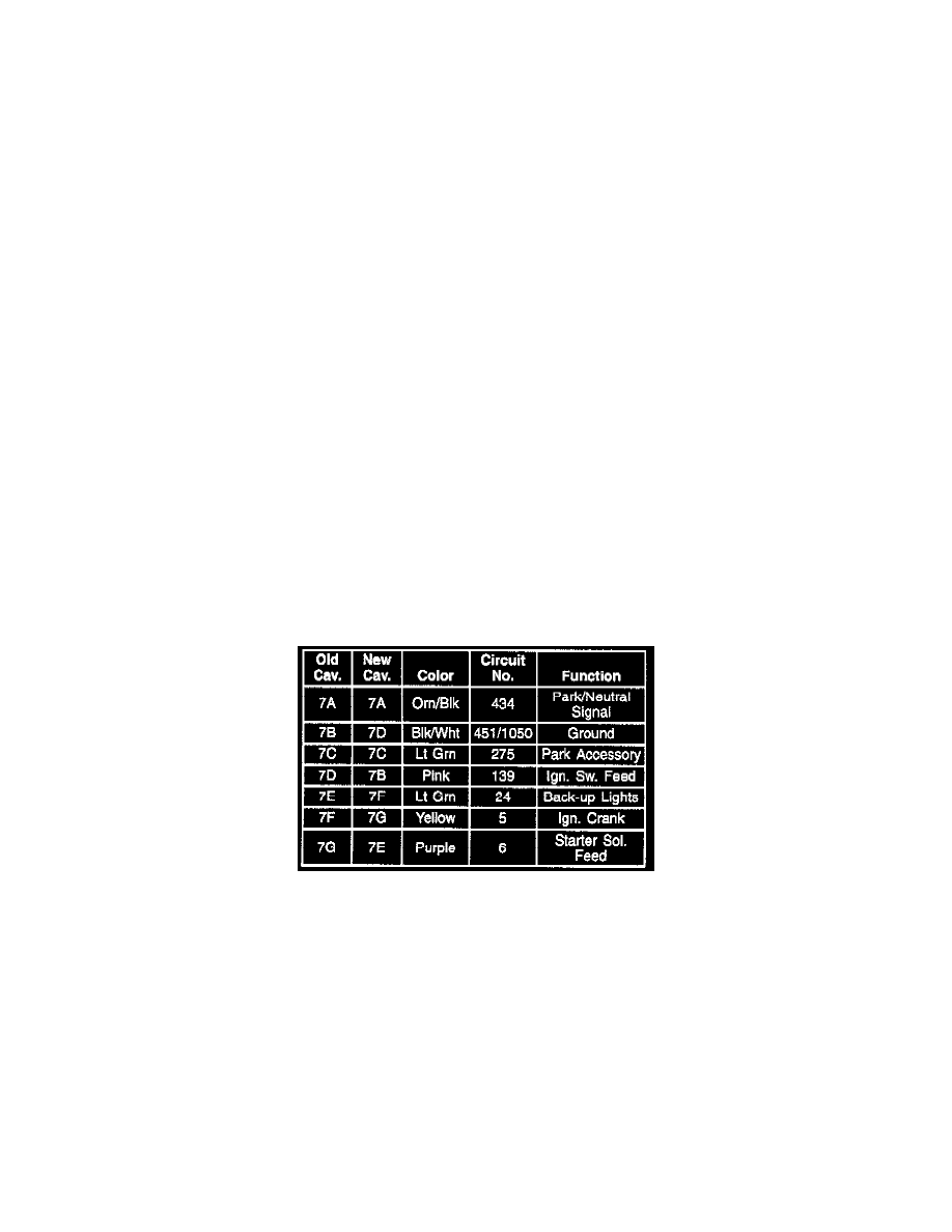
Indexing the wires:
Service Procedure
Use the following procedure to install the new switch and connector kit:
1.
Disconnect the negative battery cable. Remove the air cleaner assembly for access to the switch.
2.
Disconnect the park/neutral switch connector. Remove and discard the existing switch. Make sure to mark the original cavity numbers on the two
light green wires, so that they can go into the correct new terminal locations, Cut off the old connector, leaving as much wire length as possible.
3.
Slide the seals onto the wires, then install the new terminals. Be sure to properly crimp and solder the connections. The yellow and purple wires
will use the large terminals and seals. The remaining wires will use the small terminals and seals.
4.
Using the chart above, install the wires into the correct terminals in the new connector. Install the seal included with the connector. Install the new
TPA.