
Lumina APV V6-3800 3.8L (1994)
Crankshaft Position Sensor: Service and Repair
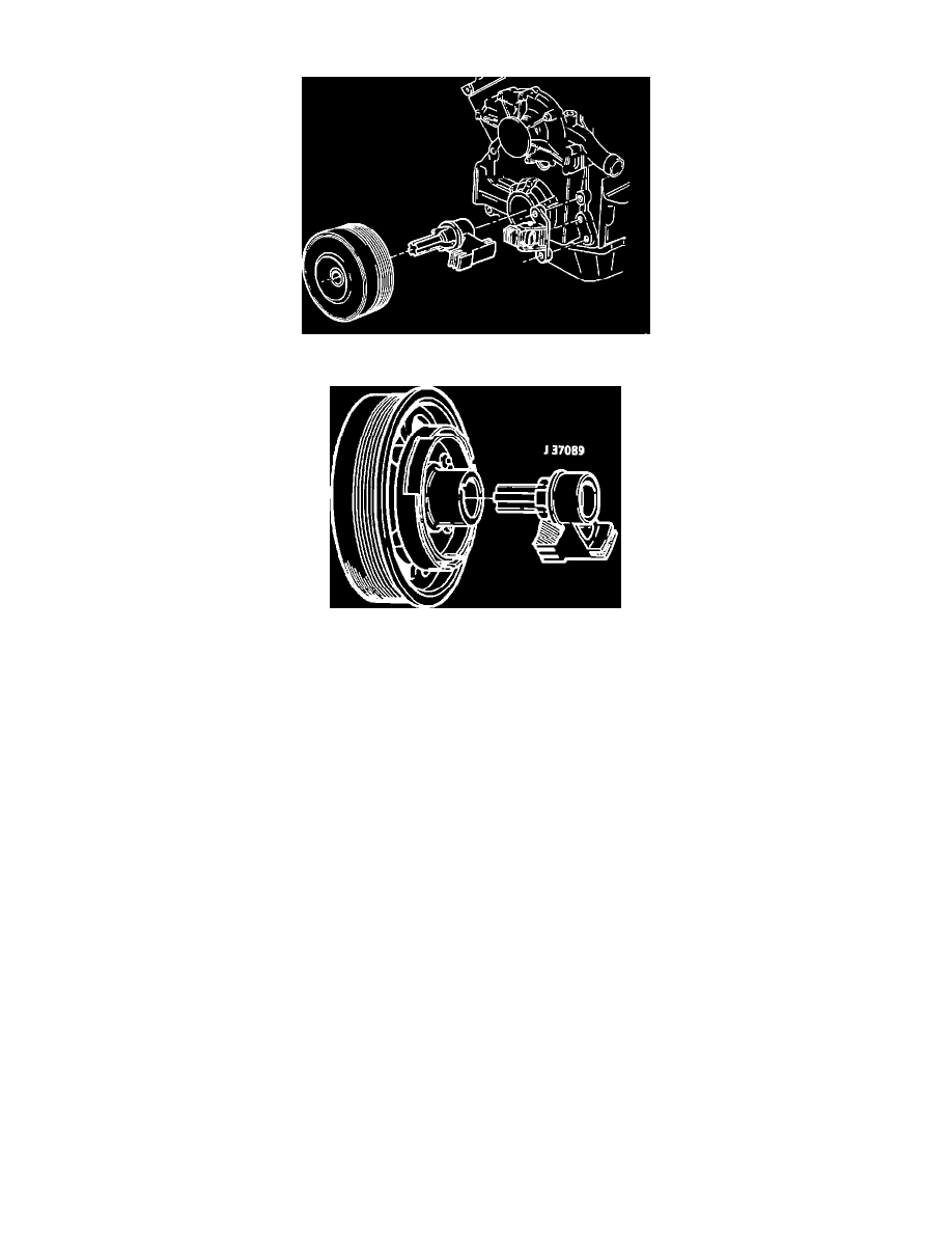
Crankshaft Sensor Positioning
Special Tool; Assembly
The harmonic balancer on these engines is now press fit on to the crankshaft and requires the use of tool J-38197 for removal. The procedure to be used
when replacing the crank sensor is as follows:
REMOVAL:
1.
Disconnect the serpentine belt from the crankshaft pulley.
2.
Raise the vehicle on the hoist.
3.
Remove the right front tire and wheel assembly.
4.
Remove the right inner fender access cover.
5.
Using a 28 mm socket, remove the crankshaft harmonic balancer retaining bolt.
6.
Remove the crankshaft harmonic balancer using tool J-38197.
7.
Remove the foreign object deflector (DO NOT use a pry bar).
8.
Disconnect the sensor electrical connector.
9.
Remove the sensor and pedestal from the block face.
10.
Remove the sensor from the pedestal.
INSTALLATION:
1.
Loosely install the crankshaft sensor on the pedestal.
2.
Position the sensor with the pedestal attached on tool J-37089.
3.
Position the tool on the crankshaft.
4.
Install the bolts to hold the pedestal to the block face, torque to 30 N-m (22 lb.ft.).
5.
Torque the pedestal pinch bolt to 4 N-m (35 lb. in.).
6.
Remove tool J-37089.
7.
Install the foreign object deflector.
8.
Place tool J-37089 on the harmonic balancer and rotate the tool. If any vane of the harmonic balancer touches the tool, replace the balancer
assembly.
9.
Install the balancer on the crankshaft.
10.
Apply thread sealer GM # 1052080 or equivalent to threads of the crankshaft balancer bolt. Using J-36660 Torque Angle Meter, torque the bolt to
150 N-m + 76 degrees (110 lb.ft. + 76 degrees).