
Luv 2WD L4-110 1800cc (1982)
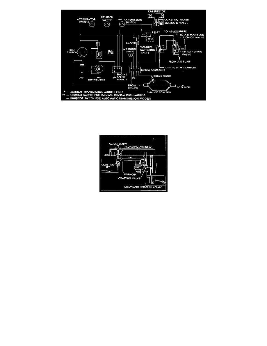
Fig.24 - Coasting Richer & Over Temperature Control System
This system, Figs. 21 through 24, uses a separate fuel system which momentarily enriches the air fuel mixture while the engine is coasting to
obtain complete combustion of the exhaust gases. It consists of a solenoid valve in the carburetor connected in series with switches which detect
engine coasting conditions.
Fig.25 - Coasting Richer System Solenoid Valve
The solenoid valve is installed in the secondary side of the carburetor and supplies additional fuel into the engine when the valve is opened, Fig.
25. When it opens, the additional fuel drawn out from the float chamber by engine vacuum is metered through the coasting jet and mixed with air
supplied through the coasting bleed. The air fuel mixture is then supplied through the coasting valve and into the lower part of the secondary
throttle valve. As a result, the air-fuel mixture becomes momentarily enriched to promote efficient recombustion of the exhaust gases in the
exhaust manifold, thus reducing the hydrocarbon and carbon monoxide content in' the exhaust gases. When the mode of engine operation changes
from coasting to normal, the coasting richer circuit opens and the solenoid valve is deactivated.
Actuation of the solenoid valve is determined by the following switches when they turn on:
a. 1972-75 all and 1976-81 except California, models - Accelerator switch, clutch switch (1976-77), clutch relay switch (1972-75, turns on when
clutch pedal is depressed) and 3rd, 4th gear switch.
b. 1976-77 California models with manual transmission - Accelerator switch, clutch switch, transmission neutral switch and engine speed sensor.
c. 1976-77 California models with automatic transmission - Accelerator switch, inhibitor switch and engine speed sensor.