
Luv 4WD L4-110 1800cc (1982)
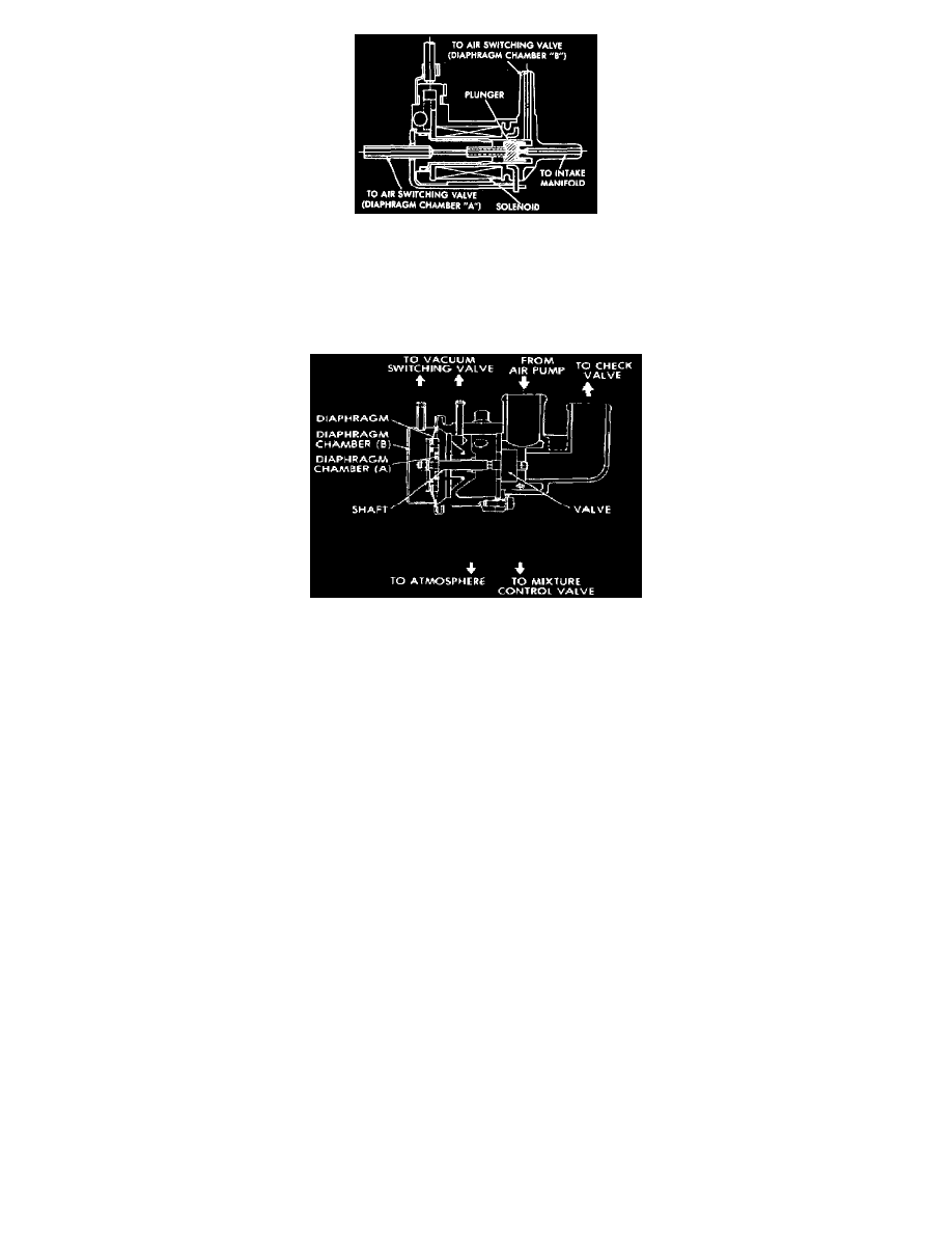
Fig.36 - Vacuum Switching Valve
The vacuum switching valve, Figs. 35 and 36, used in this system, has an electrically controlled solenoid plunger. When the catalytic converter
temperature is over about 1350° F., the solenoid plunger is energized and the vacuum switching valve connects the diaphragm chamber "B" of the
air switching valve, Fig. 34, to intake manifold allowing manifold vacuum to be applied to chamber "B". When the solenoid plunger is
de-energized, the port is closed, so diaphragm chamber "B" of air switching valve is connected to diaphragm chamber "A".
Fig.37 - Air Switching Valve
The air switching valve, Fig. 37, is used to switch air flow from the air pump and is controlled by manifold vacuum and air pump pressure which
are switched by the air switching valve. When air pump pressure is applied to diaphragm chamber "B" through the vacuum switching valve, the air
from the air pump flows to the check valve. When manifold vacuum is applied to diaphragm chamber "B," the valve closes air flow to the check
valve and diverts it to atmosphere.
A thermo sensor is installed on the front side of the converter and is covered with a stainless steel sheath. Sensing electrical resistance of the
thermo sensor, a thermo controller sends ON and OFF signals to the vacuum switching valve, warning lamp and buzzer. When the catalyst
temperature reaches about 1350° ., the controller sends an ON signal to the vacuum switching valve, and when temperature exceeds about 1830°
F, it sends an ON signal to the warning lamp and buzzer.